2. Disconnect security seals on the Transmitter Electronics Enclosure (see Figure 3-11),
loosen the end cap security latches using a 3 mm Allen wrench (see Figure 3-12) and
remove both end caps from the Transmitter Electronics Enclosure.
3. If replacing the CPU Module (terminal end of the enclosure) or the Optional I/O
Module, use a 6 mm flat blade screw driver and disconnect the CPU Module terminal
blocks (or the optional I/O Module terminal blocks).
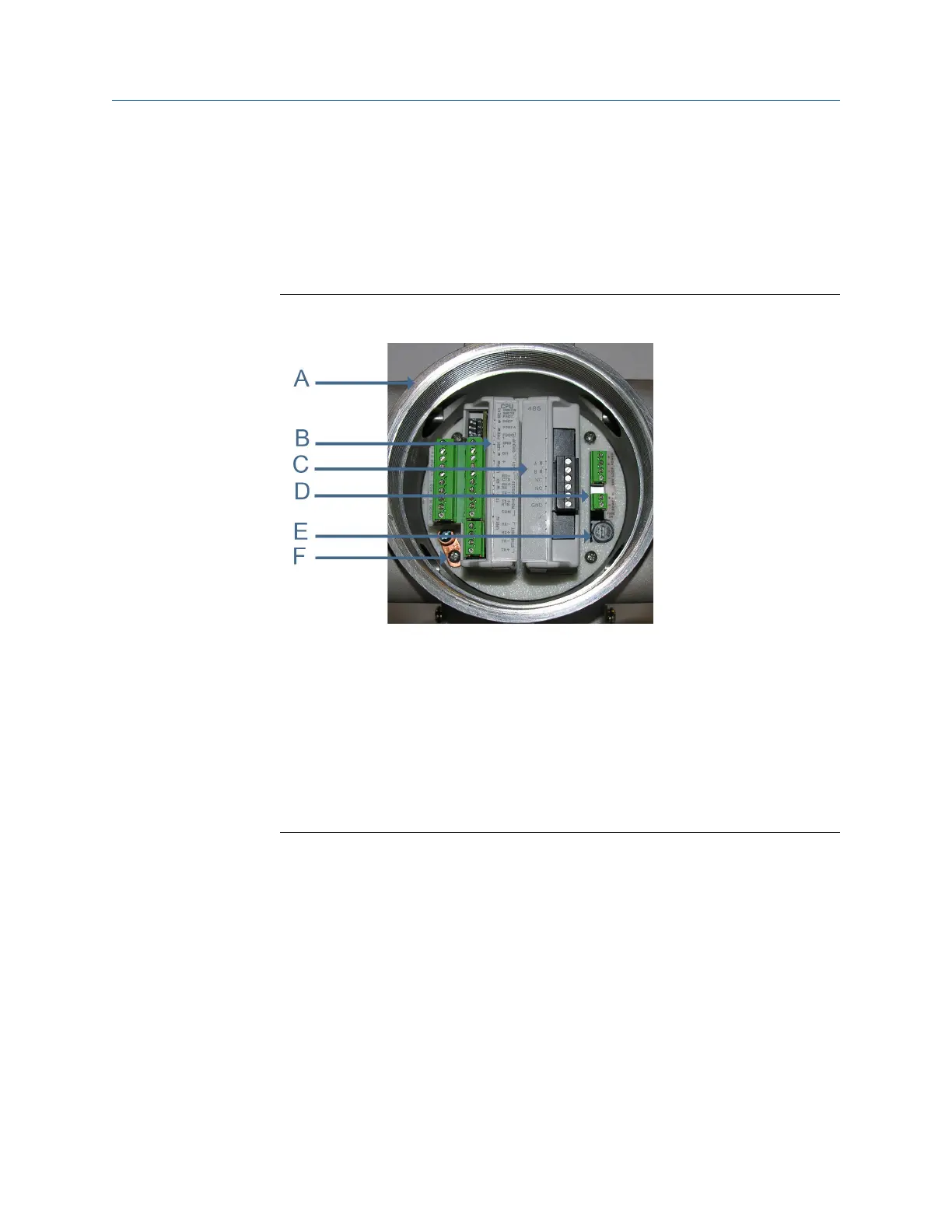
CPU or I/O Module replacementFigure 3-17:
A. Terminal end of Transmitter Electronics Enclosure
B. CPU Module
C. Optional I/O Module
D. Power Supply board
E. Fuse
F. Internal chassis ground
Meter repairs
70 Gas Ultrasonic Flow Meters

 Loading...


