Safety
Information
Product
Information
Mechanical
Installation
Electrical
Installation
Getting
Started
Basic
parameters
Running the
Motor
Optimization
SMARTCARD
Operation
Onboard
PLC
Advanced
Parameters
Technical
Data
Diagnostics
UL
Information
16 Quantum MP User Guide
www.emersonct.com Issue: A4
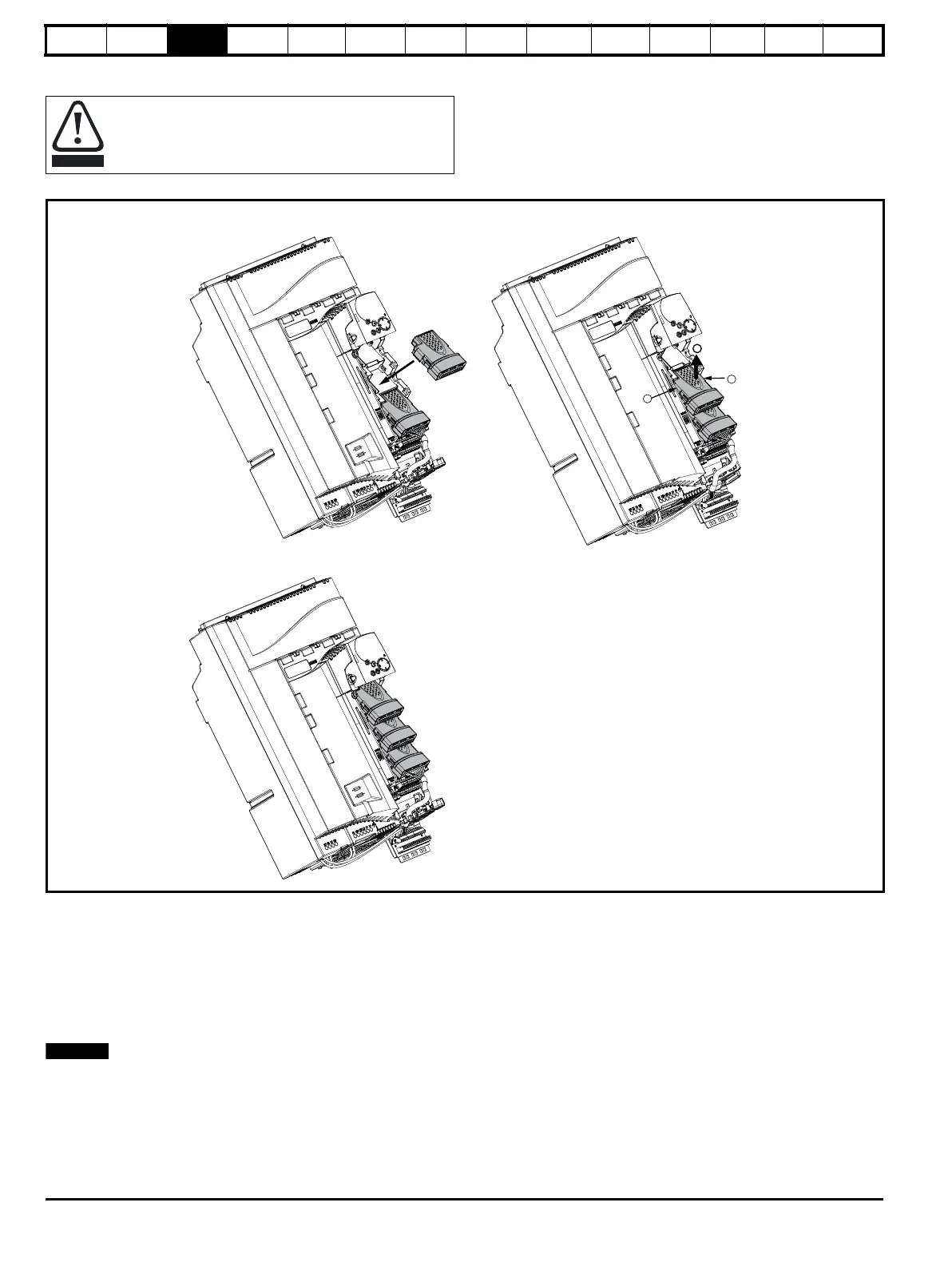
3.3.3 Installation and removal of a Solutions Module
Figure 3-3 Installation and removal of the Solutions Module - Size 1 shown
To install the Solutions Module in either a Quantum MP size 1 or size 2
drive, press down in the direction shown above until it clicks into place.
To remove the Solutions Module, press inwards at the points shown (A)
and pull in the direction shown (B).
The drive has the facility for all three Solutions Module slots to be used
at the same time, as illustrated. The SM-I/O 120V module needs to stay
in Slot 3.
It is recommended that the Solutions Module slots are used in the
following order: slot 2 and slot 1.
Please power down the drive before removing / installing the
Solutions Module. Failure to do so may cause damage to
product
SM-I/O 120V Module
in slot 3
Solution Module
in slot 1
Solution Module
in slot 2
Installing Solutions Module
Three Solutions Modules installed
Removing Solutions Module
A
A
B