Safety
Information
Product
Information
Mechanical
Installation
Electrical
Installation
Getting
Started
Basic
parameters
Running the
Motor
Optimization
SMARTCARD
Operation
Onboard
PLC
Advanced
Parameters
Technical
Data
Diagnostics
UL
Information
52 Quantum MP User Guide
www.emersonct.com Issue: A4
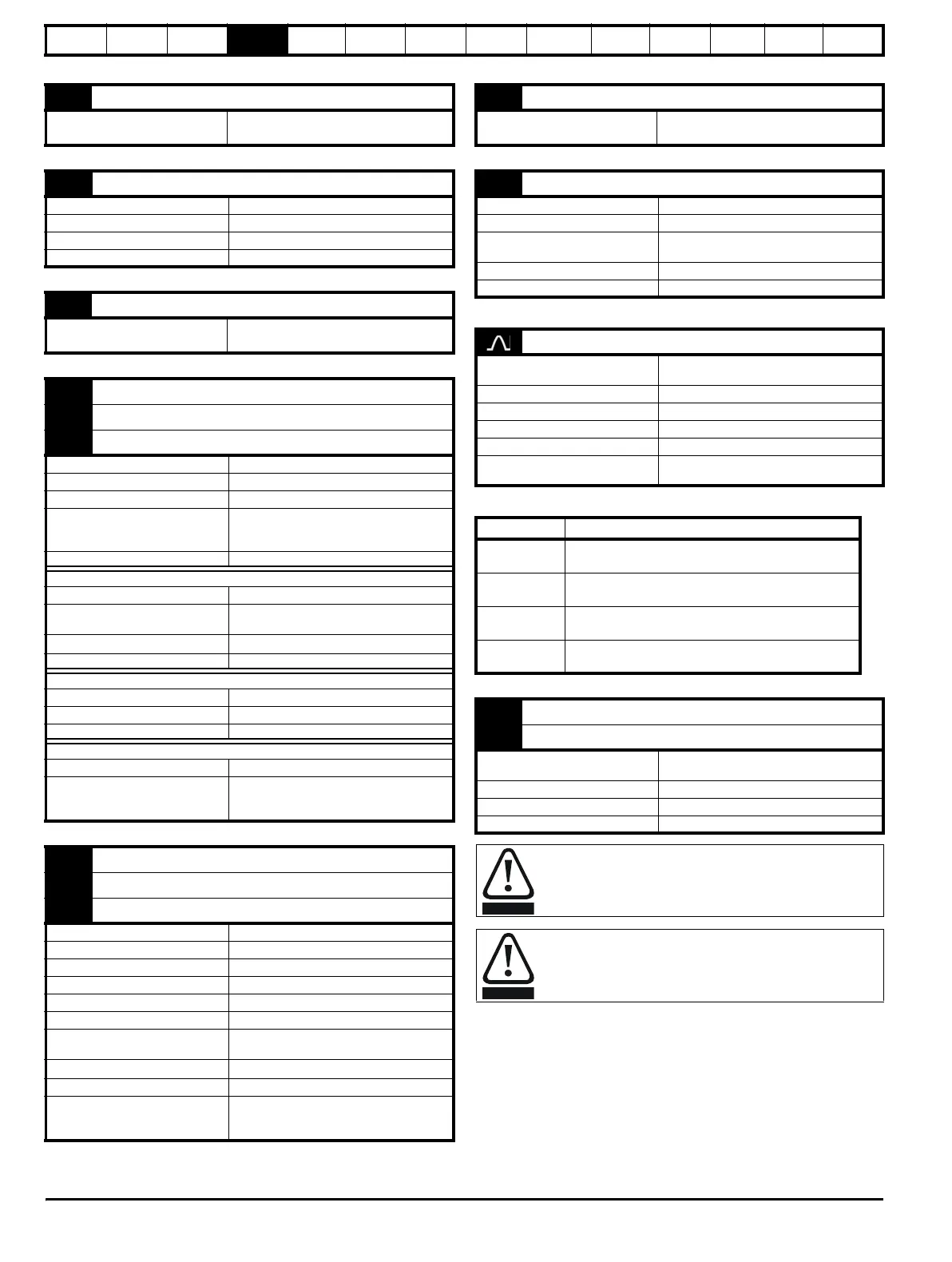
21 0V common
Function
Common connection for all external
devices
22 +24V user output
Function Supply for external digital devices
Nominal output current 200 mA (including all digital I/O)
Maximum output current 240 mA (including all digital I/O)
Protection Current limit and trip
23 0V common
Function
Common connection for all external
devices
24 Digital I/O 1
25 Digital I/O 2
26 Digital I/O 3
Terminal 24 default function AT SPEED output
Terminal 25 default function Not programmed
Terminal 26 default function Not programmed
Type
Positive or negative logic digital inputs,
positive or negative logic push-pull outputs
or open collector outputs
Input / output mode controlled by... Pr 8.31, Pr 8.32 and Pr 8.33
Operating as an input
Logic mode controlled by... Pr 8.29
Absolute maximum applied voltage
range
30V, -18V relative to 0V
Impedance
6k
Input thresholds 10.0V 0.8V
Operating as an output
Open collector outputs selected Pr 8.30
Nominal maximum output current 200 mA (total including terminal 22)
Maximum output current 240 mA (total including terminal 22)
Common to all modes
Voltage range 0V to +24V
Sampling period
250
s if configured with the destination as
Pr 6.35 or Pr 6.36. 4 ms for all other
destinations
27 Digital input 1
28 Digital input 2
29 Digital input 3
Terminal 27 default function Not programmed
Terminal 28 default function LOCAL/REMOTE select
Terminal 29 default function Not programmed
Type of input Negative or positive logic digital inputs
Logic mode controlled by... Pr 8.29
Voltage range 0V to +24V
Absolute maximum applied voltage
range
+30V, -18V relative to 0V
Impedance
6k
Input thresholds 10.0V 0.8V
Sampling period
250
s if configured with the destination as
Pr 6.35 or Pr 6.36. 4 ms for all other
destinations
30 0V common
Function
Common connection for all external
devices
31 ENABLE
Function Drive enable
Type Positive or negative logic digital input
Absolute maximum applied voltage
range
+30V, -18V relative to 0V
Input threshold 10.0V 0.8V
Sampling period 4 ms
Drive commissioning output
Function
Instantaneous armature current
feedback
Type of output Unipolar single-ended voltage
Full scale voltage range 10V ±5%
Full scale range 2.3 X Drive Rated Current [Pr 11.32]
Maximum offset 7 mV
Protection
~25 mA max. Short circuit protection to
ground (0V).
Model Full scale range of drive commissioning output
QMP45A4(R)
2.30 x Drive rated current
(PR 11.32)
QMP75A4(R)
2.42 x Drive rated current
(PR 11.32)
QMP155A4(R)
2.30 x Drive rated current
(PR 11.32)
QMP210A4(R)
2.41 x Drive rated current
(PR 11.32)
41 Tachgenerator positive input
42 Tachgenerator negative input
Function
Speed feedback inputs for
tachgenerator feedback device
Maximum voltage 300V
Feedback scaling controlled by Pr 3.51 (Fb02, 0.72)
Sampling period 4 ms
Status relay contacts are over-voltage category II.
A fuse or other over-current protection should be installed to
the relay circuit.