Safety
Information
Product
Information
Mechanical
Installation
Electrical
Installation
Getting
Started
Basic
parameters
Running the
Motor
Optimization
SMARTCARD
Operation
Onboard
PLC
Advanced
Parameters
Technical
Data
Diagnostics
UL
Information
Quantum MP User Guide 53
Issue: A4 www.emersonct.com
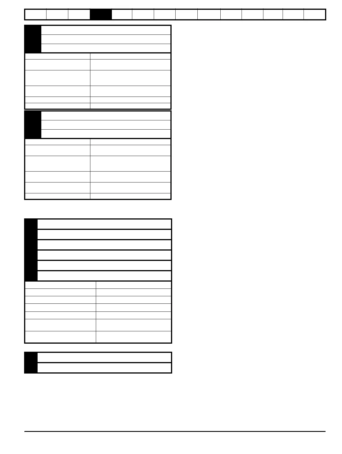
4.16.3 Feedback device connections
Ab, Fd, Fr encoders
51 Relay 1 common
52 Relay 1 normally closed
53 Relay 1 normally open
Default function Drive OK indicator
Contact voltage rating
240 Vac, installation over-voltage category
II
Contact maximum current rating
5 A AC 240 V
5 A DC 30 V resistive load
0.5A DC 30 V inductive load (L/R = 40 ms)
Contact minimum recommended
rating
12 V, 100 mA
Default contact position Closed when power on and drive OK
Sampling period 4 ms
61 Relay 2 common
62 Relay 2 normally closed
63 Relay 2 normally open
Default function Contactor enable
Contact voltage rating
240 Vac, installation over-voltage category
II
Contact maximum current rating
5A AC 240V
5A DC 30V resistive load
0.5A DC 30V inductive load (L/R = 40 ms)
Contact minimum recommended
rating
12V, 100 mA
Default contact position
Closed when AC or DC contactor is
required to be closed.
Sampling period 4 ms
A Channel A, Frequency or Forward inputs
A\ Channel A\, Frequency\ or Forward\ inputs
B Channel B, Direction or Reverse inputs
B\ Channel B\, Direction\ or Reverse\ inputs
Z Marker pulse channel Z
Z\ Marker pulse channel Z\
Type EIA 485 differential receivers
Maximum input frequency 500k Hz
Line loading <2 unit loads
Line termination components
100for 2 - 5V range(switchable)
Working common mode range +12V to –7V
Absolute maximum applied voltage
relative to 0V
25V
Absolute maximum applied differential
voltage
25V
+ + Supply
0V 0V