Safety
Information
Product
Information
Mechanical
Installation
Electrical
Installation
Getting
Started
Basic
parameters
Running the
Motor
Optimization
SMARTCARD
Operation
Onboard
PLC
Advanced
Parameters
Technical
Data
Diagnostics
UL
Information
68 Quantum MP User Guide
www.emersonct.com Issue: A4
This is the final speed demand at the input to the speed regulator formed
by the sum of the ramp output and the hard speed reference (if the hard
speed reference is enabled). If the drive is disabled this parameter will
show 0.0.
The speed feedback can be taken from the drive encoder port or
tachometer or armature voltage or a position feedback module installed
in any slot as selected with Fb01 (Pr 0.71, 3.26). di05 (Pr 0.40, 3.02)
shows the level of the speed feedback selected for the speed controller.
Display filtering is active when this parameter is viewed with one of the
drive keypads. The value held in the drive parameter (accessible via
comms or an option module) does not include this filter, but is a value
that is obtained over a sliding 16 ms period to limit the ripple seen in this
parameter value. The speed feedback value includes encoder
quantization ripple given by the following equation:
Ripple in di05 (Pr 0.40, 3.02) = 60 / 16 ms / (ELPR x 4)
Where ELPR is the equivalent encoder lines per revolution as defined
below:
For example a 4096 line Ab type encoder gives a ripple level of 0.23rpm.
The 16 ms sliding window filter is always applied to the value
shown in di05 (Pr 0.40, 3.02), but this sliding window filter is not
normally applied to the actual speed feedback used by the speed
controller or the drive encoder reference system (Pr 3.43 to
Pr 3.46). The user may apply a filter to the speed controller input and the
drive encoder reference system input if required by setting Pr 3.42 to the
required filter time. The encoder ripple seen by the speed controller is
given by:
Encoder speed ripple = 60 / Filter time / (ELPR x 4)
If Pr 3.42 is set to zero (no filter) the ripple seen by the speed controller
and drive encoder reference system is given by:
Encoder speed ripple = 60 / 250s / (ELPR x 4)
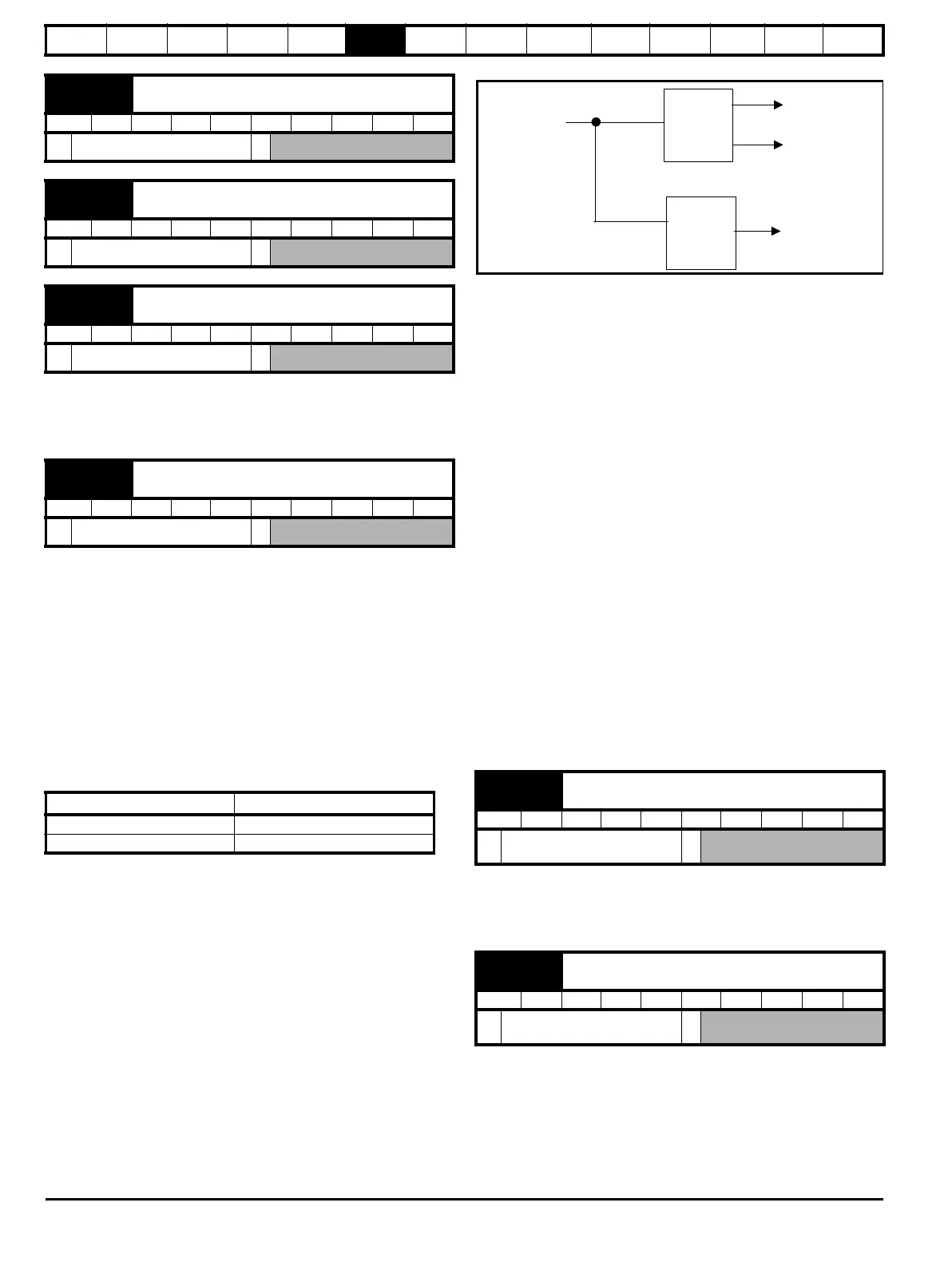
Figure 6-1
Figure 6-1 shows the filter arrangement. It should be noted that the
same filtering is provided at the speed controller input and for di05 (Pr
0.40, 3.02) when the feedback is obtained from an option module, but
the variable length window filter is controlled by Pr x.19.
It is not advisable to set the speed feedback filter too high unless it is
specifically required for high inertia applications with high controller
gains because the filter has a non-linear transfer function. It is preferable
to use the current demand filters (see Pr 4.12 or Pr 4.23) as these are
linear first order filters that provide filtering on noise generated from both
the speed reference and the speed feedback. It should be noted that any
filtering included within the speed controller feedback loop, either on the
speed feedback or the current demand, introduces a delay and limits the
maximum bandwidth of the controller for stable operation.
The speed ripple can be quite high, for example with a 4096 line encoder
the speed ripple is 14.6rpm, but this does not define the resolution of the
speed feedback which is normally much better and depends on the
length of the measuring period used to obtain the feedback. This is
shown in the improved resolution of the value accessible in di05
(Pr 0.40, 3.02) which is measured over 16 ms, i.e. a resolution of
0.23rpm with a 4096 line encoder. The speed controller itself
accumulates all pulses from the encoder, and so the speed controller
resolution is not limited by the feedback, but by the resolution of the
speed reference. If a SINCOS encoder is used from an option the
encoder speed ripple is reduced by a factor of 2(
2-Interpolation bits
). For
example with the nominal 10 bits of interpolation information, the speed
ripple is reduced by a factor of 256. This shows how a SINCOS encoder
can reduce noise caused by encoder quantization without any filtering in
the speed feedback or the current demand, so that high gains may be
used to give high dynamic performance and a very stiff system.
The output of the speed regulator is a torque demand given as a
percentage of rated motor torque. This is then modified to account for
changes in motor flux if field weakening is active, and then used as the
torque producing current reference.
The torque demand can be derived from the speed controller and/or the
torque reference and offset. The units of the torque demand are a % of
rated torque.
di02
{0.37, 1.03}
Pre-ramp reference
RO Bi NC PT
±MAX_SPEED_REF rpm
di03
{0.38, 2.01}
Post ramp reference
RO Bi NC PT
±SPEED_MAX rpm
di04
{0.39, 3.01}
Final speed reference
RO Bi FI NC PT
±SPEED_MAX rpm
di05
{0.40, 3.02}
Speed feedback
RO Bi FI NC PT
±SPEED_MAX rpm
Position feedback device ELPR
Ab number of lines per revolution
Fd, Fr number of lines per revolution / 2
di06
{0.41, 3.04}
Speed controller output
RO Bi FI NC PT
±TORQUE_PRODUCT_
CURRENT_MAX rpm
di07
{0.42, 4.03}
Torque demand
RO Bi FI NC PT
±TORQUE_PROD_
CURRENT_MAX %
Filter
defined
by Pr
3.42
16ms
filter
From the drive
encoder port
Speed
controller
Drive encoder
reference
system
di05
0.40, 3.02
Fb09
0.79, 3.27
(Pr )
and
(Pr )