3. Remove tubes (B, C, and D) from the COe sensor assembly (I), eductor
fittings (N and H), and sensor housing (P).
4. Unfasten bayonet connector of COe thermocouple (L) and remove
thermocouple.
5. Loosen clamp screw of COe band heater (M) until the heater rotates freely
on the sensor holder.
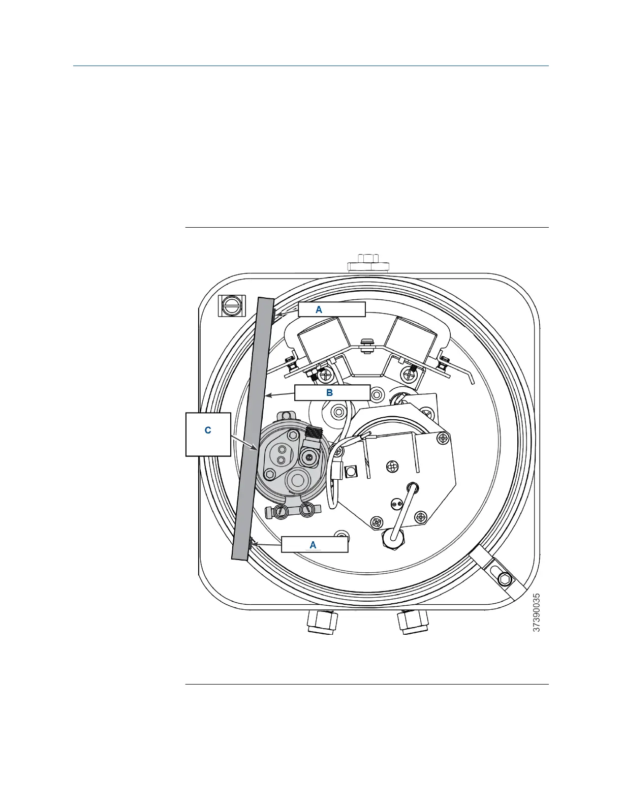
6. See Figure 10-11. Using a straight edge on the sensor holder flat, as shown,
matchmark the upper flange of sensor housing to show the correct
alignment of the sensor holder (J).
Figure 10-11: Alignment of COe Sensor Assembly
A. Matchmark
B. Straightedge
C. Sensor holder flat
Maintenance and service Manual
December 2022 00809-0500-4880
256 Emerson.com/Rosemount