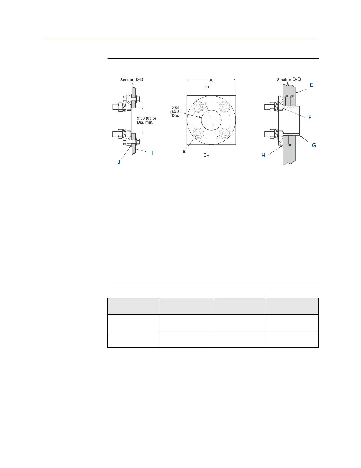
Figure 2-2: Adapter Plate Installation
Dimensions are in inches with millimeters in parentheses. Only adapter
plate is furnished by Emerson.
A. Plate size (see Table 2-4)
B. Stud size (see Table 2-4)
C. Bolt circle diameter (see Table 2-4)
D. Cross section
E. Masonry stack wall
F. Field weld pipe to adapter plate
G. Pipe 3 in. schedule 40. Sleeve length optional.
H. Bolt adapter plate to outside wall surface. Joint must be air-tight.
I. Metal stack or duct wall
J. Weld or bolt adapter plate to metal wall. Joint must be air-tight.
K. Metal wall stack or duct construction
L. Masonry wall stack construction
Table 2-4: Adapter Plate Kit-Mounting Dimensions
Type part
number
(1)
Plate size "A" Stud size "B" Bolt circle
diameter "C"
ANSI (PN
4512C34G01)
6.00 in. (152 mm) ⅝-11 UNC-2A 4.75 in. (121 mm)
DIN (PN
4512C36G01)
7.5 in. (191 mm) M-16 x 2.0-6g 5.71 in. (145 mm)
(1) Part numbers for adapter plates include attaching hardware.
3. Use the pipe or wall mounting hardware to mount a remote electronics
housing.
Choose a location that does not exceed the length of the electronics cable
ordered.
4. Ensure the conduits drop vertically from the transmitter and the conduit is
routed below the level of the conduit ports on the housing to form a drip
loop.
Manual
Install
00809-0500-4880 December 2022
Rosemount OCX8800A 31