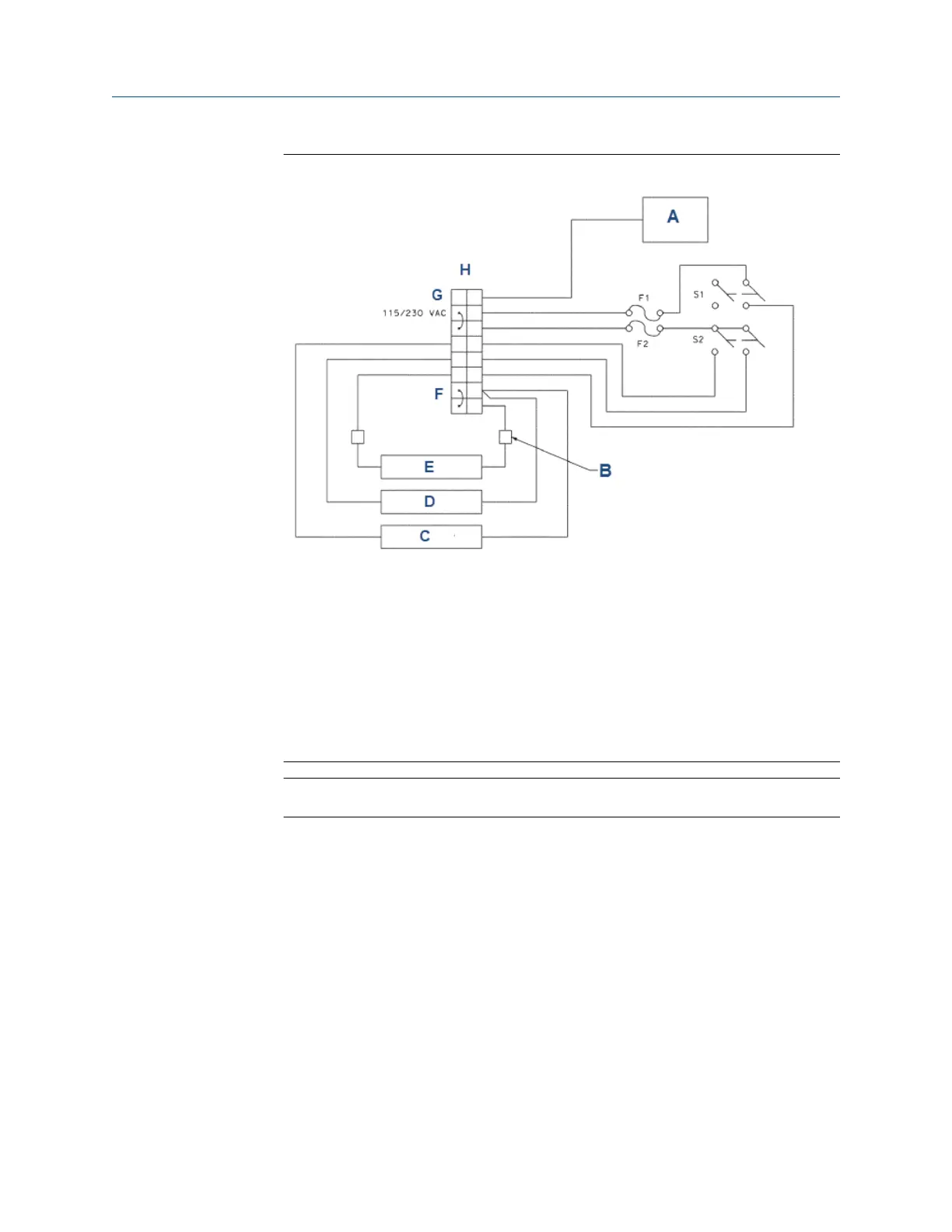
Figure 4-1: Power wiring
Model option -11: 115 Vac only
Model option -12: 230 Vac only
A. Front panel
B. Connector
C. Air pump
D. Sample pump
E. Reagent pump
F. Neutral
G. Ground
H. Terminal block
Important
Leave the pump power switches off until ready to start up the unit.
See Startup.
4.3
Power
Wire AC mains power supply to the power supply board, which is mounted vertically on the
left hand side of the transmitter enclosure beneath the gray plastic cover.
Procedure
1. To remove the cover, grab it by the upper edges and pull straight out.
The power connector is at the bottom of the board. See Alarm relay connection.
2. Bring the power cable through the conduit opening just below the connector.
3. Unplug the connector from the board and wire the power cable to it.
Lead connections are marked on the connector. (L is live or hot; N is neutral; the
ground connection has the standard symbol.)
Wiring Reference Manual
January2023 00809-0200-3415
18 Emerson.com/Rosemount

 Loading...


