28743-0-0711 Page 13
DIRECT VENT AND COLINEAR VENT EXAMPLES
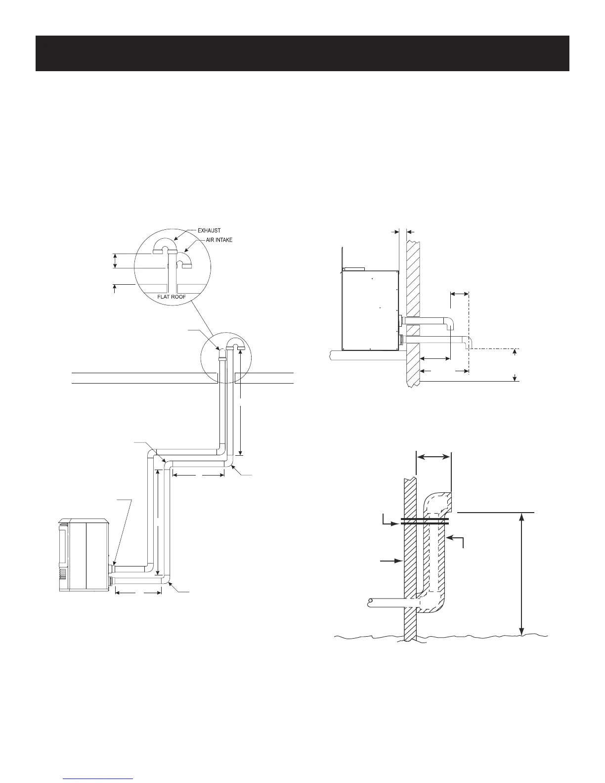
Figure 5 displays a two-pipe installation. Because the distance
from the heater to the rst elbow is more than 6 inches, the rst 90°
elbow does need to be considered into the total vent length. The
equivalent length of the second 90° elbow also needs to be added
to the total length. The third elbow also needs to be included. The
equivalent length of the PTrap does not need to be added since it
is the termination. The total horizontal vent length of the ue sys-
tem is 11 feet, and the total vertical length is 20 feet. The three 90°
elbows are equivalent to 9 feet, bringing the total to 40 feet.
Note: The exhaust must be a minimum of 3 inches above the inlet
air pipe. The ue must be at least 12 inches from the roof line, and
it is recommended to be at least 12 inches above the maximum
expected snow level as indicated in Figures 5 through 8.
12” MIN TO GRADE
(RECOMMENDED 12” MIN.
TO MAX EXPECT SNOW LEVEL)
6” MIN.
9” MIN.
3” MIN.
2” MIN.
Figure 6
3” MIN.
12” MIN. TO ROOF
(RECOMMENDED 12”
MIN TO MAX. EXPECTED
SNOW LEVEL)
PTRAP
90° ELBOW
3’
COLINEAR ADAPTER
5’
10’
FIRST 90° ELBOW
DOES NOT GET COUNTED
WHEN WITHIN 6” FROM THE
BACK OF HEATER
H=5’+6’ =11’
V=10’ +10’ =20’
(3) 90°=9’
=40’TOTA L
6’
90° ELBOW
3’
10’
Figure 5
Calculation example of vent run maximum 40 feet
Note: Exhaust must be a
minimum of 3 inches above
air intake inlet.
6” MIN.
12” MAX.
SUPPORT
OUTSIDE
WALL
1/2”
ARMAFLEX
INSULATION OR
EQUIVALENT
(IF REQUIRED)
12” ABOVE
MAXIMUM
EXPECTED
SNOW LEVEL
Figure 7