28743-0-0711 Page 25
BAY WINDOW MANTIS LOG SET INSTALLATION INSTRUCTIONS
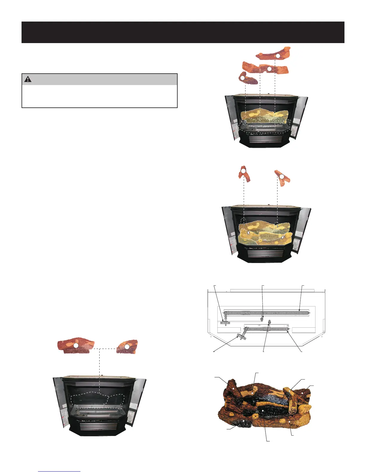
Log Installation
Positioning of the logs is critical to the safe and clean operation of
this heater. If the logs are not placed in the proper position, the ap-
pliance can soot, and create an unsafe operating condition.
CAUTION
Do not handle these logs with your bare hands! Always
wear gloves to prevent skin irritation. After handling the
logs, wash your hands gently with soap and water.
1. To access the log set parcel, lift off the top panel.
2. Pivot the left and right panels open.
3. Unhook the main door latches located on the right and left
side of the heater, then remove the door.
4. Connect the Rear Left Log (A) and the Rear Right Log (B).
Place the logs behind the rear burner. The logs should be all
the way to the back of the rebox. See Figure 43.
5. Place the Front Left Log (C) into the groove on (A) Log, and
locate into the left corner of rebox. See Figure 44.
6. Place the Middle Log (D) over the ame sensors that are lo-
cated in the middle of the rebox. The Middle Log (D) should
be positioned as far to the right side of the rebox as pos-
sible.
7. Locate the Front Right Log (E) in the right front corner of re-
box. The Front Right Log (E) should t snug into the corner.
8. Place the Top Left Log (F) onto the pin on (A) Log. The “legs”
of (F) Log will rest on (D) Log. See Figure 45.
9. Place the Top Right Log (G) onto the pin on (B) Log. The
“legs” of (G) Log will rest on (E) Log.
10. Place the door assembly on the heater and secure with the
main door latches that are located on right and left sides of the
heater.
11. Close the left and right panels.
12. The installation of the log set is complete.
13. Verify that the logs are not in contact with the ame sensor.
Interference with the ame sensor will effect the operation.
Log Placement
Figure 43
Log Placement
Figure 44
Log Placement
Figure 45
PLATE - LOG SUPPORT
FRONT HOT SURFACE IGNITOR
REAR HOT SURFACE IGNITOR REAR FLAME SENSOR
FRONT FLAME SENSOR
REAR BURNER
FRONT BURNER
Firebox Layout
Figure 46
REAR LEFT LOG (A)
TOP RIGHT LOG (G)
FRONT RIGHT LOG (E)
CENTER LOG (D)
FRONT LEFT LOG (C)
TOP LEFT LOG (F)
REAR RIGHT LOG (B)
Log Assembly
Figure 47