28743-0-0711Page 24
GAS CONNECTION INSTALLATION
CAUTION
The gas supply line to the heater must be installed
under conditions which will allow for easy removal of
the heater from its location for servicing of the heat-
er. For replace insert installation, incorporate a loop
into the exible gas line.
Under no circumstances should the gas supply line
to the appliance be installed in a way that would pre-
vent the appliance from being serviced or inspected.
GAS SUPPLY LINE TO HEATER
1. Pull the factory installed exible gas line through the hole in
the back panel. See Figures 40 and 41.
2. Connect the gas supply line to exible gas hose. Ensure that
exible gas hose is not kinked after tting gas supply line. Any
excess exible line can be pushed back into the heater.
3. Place rubber grommet that is supplied in hardware packet
over the exible gas line and secure in the hole in the back of
the appliance.
Gas Connection - In-Wall Units - Fireplace Mantis ONLY
1. Remove the access plate on the left side of the cabinet by
removing three screws as shown in Figure 42. Put the screws
aside.
2. Push the factory supplied exible gas line through the access
hole on the side.
3. Remove the knockout from the access plate and insert the
exible gas line through the hole.
4. Secure the access plate to the cabinet with three screws re-
moved in Step 1.
5. A plastic push in plug is supplied in the hardware package,
insert the plug into the 1-3/8 inch hole in the back of the unit.
6. Insert the rubber grommet into the hole in the access plate to
protect the exible gas line.
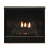
Figure 40 - Fireplace Mantis
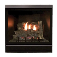
Figure 41 - Bay Window Mantis
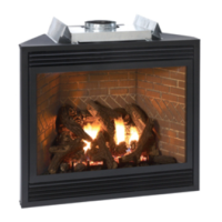
Figure 42
Gas Connection, Fireplace Mantis In-Wall Units