Electrical connection Cerabar PMC11, PMC21, PMP11, PMP21, PMP23
22 Endress+Hauser
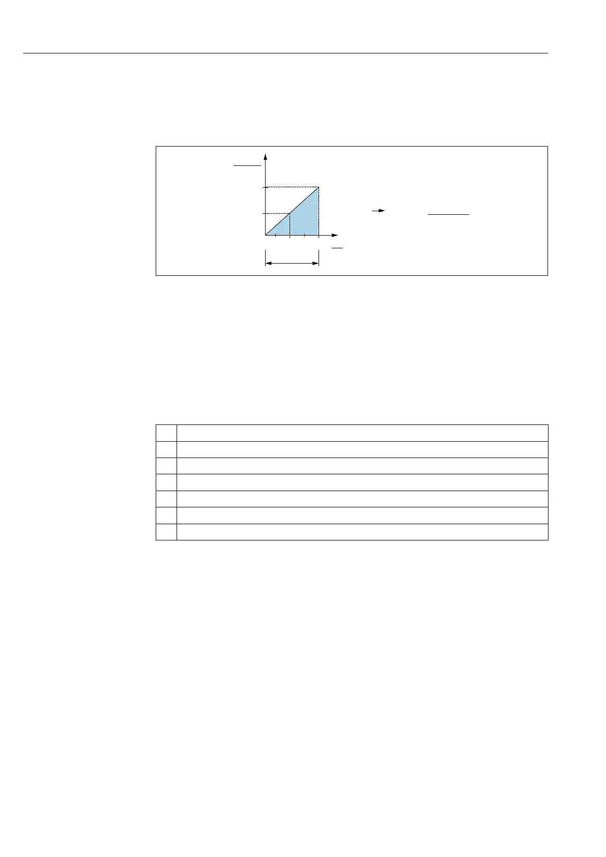
6.3.1 Load (for 4 to 20 mA devices )
In order to guarantee sufficient terminal voltage in two-wire devices, a maximum load
resistance R
L
(including line resistance) must not be exceeded, depending on the supply
voltage U
B
of the supply unit.
[ ]W
30
20
10
1068
614
U
[V]
1
2
R
R
L
L
max
max
A0029452
1 Power supply 10 to 30 V DC
2 R
Lmax
maximum load resistance
U
B
Supply voltage
6.3.2 Load resistance (for 0 to 10 V devices)
The load resistance must be ≥ 5 [kΩ].
6.4 Post-connection check
Is the device or cable undamaged (visual check)?
Do the cables comply with the requirements ?
Do the cables have adequate strain relief?
Are all the cable glands installed, firmly tightened and leak-tight?
Does the supply voltage match the specifications on the nameplate?
Is the terminal assignment correct ?
If required: Has protective ground connection been established ?
 Loading...


