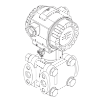
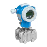
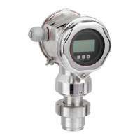
Deltabar S
Endress+Hauser 11
Safety function
Definition of the safety
function
The device's safety functions are:
• Minimum and/or maximum differential pressure monitoring; absolute and gauge pressure
(dp-gauge)
• Flow monitoring (via primary device)
• Level monitoring
Safety-related signal The safety-related signal of the Deltabar S is the analogue output signal 4 to 20 mA.
All safety functions solely refer to this output. In addition, the Deltabar S communicates via HART and
contains all HART features with additional diagnostics information.
The behavior of the output current in the event of an error depends on the settings for the messages
(Table ä 14).
The safety-related output signal is fed to a downstream logic unit, e.g. a programmable logic controller
or a limit signal transmitter where it is monitored for the following:
• Exceeding and/or undershooting of a specific limit value.
• The occurrence of a fault, e.g. error current (≤3.6 mA, ≥21.0 mA, signal cable open circuit or short-
circuit).
The following dangerous undetected failures can occur in the devices:
• An incorrect output signal which deviates from the real measured value by more than 1%, with the
output signal remaining within the 4 to 20 mA or 3.8 to 20.5 mA range.
• A settling time that is delayed by more than the specified settling time plus tolerance.
For fault monitoring, the logic unit must be able to detect HI alarms ( 21 mA) and LO alarms
( 3.6 mA).
The transmitter output is not safety-oriented during the following activities:
• Changes to the configuration
•Multidrop
– with software version < 02.20, if the parameter "bus address" (345) is set
≠ "0".
– with software version ≥ 02.20, if the parameter "current mode" (052) is set to "fixed" (onsite display
and FieldCare) or "disabled" (HART handheld terminal).
• Simulation
• Proof-test
While configuring the transmitter and performing maintenance work on Deltabar S, alternative
measures must be taken to ensure the process safety.
Restrictions for use in
safety-related applications
• Device warmup time: after device warmup, the safety functions are available after a 30-second
initialization period.
• With regard to the calculation of the SFF, a tolerance range of ±1 % was established for the deviation
of the output current in the event of a failure of a safety-related component in the pressure
transmitter. If the pressure transmitter is operated in safety-related applications, it is recommended
to increase the total performance failure, as indicated in the Technical Information (TI), by this value.
• In the case of local operation of the Deltabar S without a display and without an operating tool or
without a HART communicator, the device cannot be safely configured because the user cannot
perform a visual check. In both these situations, communication via HART alone is not sufficient.
• The Deltabar S must be locked following configuration.
• When using the Deltabar S as a subsystem of a safety function, the "Hold meas. value" setting in the
parameter "Output fail mode" (388) and also the Multidrop mode ( ä 11) may not be selected as
this option does not provide failsafe alarming.
• During commissioning, a complete function test of the safety-related functions must be performed.
• The maximum interval for proof testing (Proof Test Interval) is 5 years.
• Faulty devices must be replaced as soon as possible to minimize the possibility of multiple errors
occurring.
The failure probabilities indicated in this Safety Manual are based on a medium time to repair
(MTTR) of 8 hours.
In the event of an error, it must be ensured that the facility to be monitored remains in a safe
state or is set to a safe state.
 Loading...


