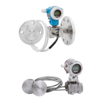
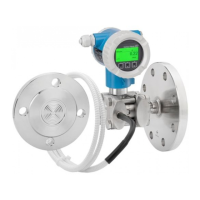
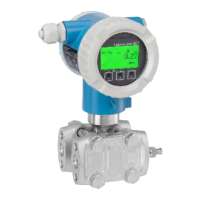
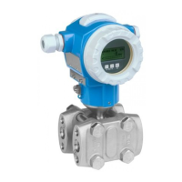
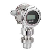
Deltabar S
Endress+Hauser 23
Locking/unlocking
Changes to the measuring system or parameters can affect the safety function.
‣ After entering all the parameters and checking the safety function, the operation of the device
must be locked.
Increased security during parameter entry
Locking
With the "Increased security during parameter entry" method, the device is locked by a password at the
end of the locking sequence.
• Via local operation or via the Field Communicator 375, 475 handheld terminal ä 16ff
• Via the operating tool ä 16ff
Unlocking
1. Select the "SAFETY CONFIRM." group.
(Menu path: (GROUP SELECTION ) OPERATING MENU SAFETY CONFIRM.).
2. Select the "Unlock" option via the SAFETY LOCK parameter.
3. Enter the password "7452" via the SAFETY PASSWORD parameter. If the password entered is
correct, the SAFETY LOCK or SAFETY LOCKSTATE parameter displays the status "Unlocked".
Standard device configuration
If you are using the "Standard device configuration" method ( ä 20), the device has to be locked via
the software and/or the hardware.
Operating Instructions BA00270P/00/EN, "Locking/unlocking operation" section.
Unlocking a SIL device
When SIL locking is active on a device, the device is protected against unauthorized operation by means
of a locking code and, as an additional option, by means of a hardware write protection switch. The
device must be unlocked in order to change the configuration, to perform proof-tests and to reset self-
holding diagnostic messages.
Proof-test Safety functions must be tested at appropriate intervals to ensure that they are functioning correctly
and are safe. The operator must determine the time intervals. The test must be carried out in such a
way that it is proven that the protective system functions perfectly in interaction with all the
components.
The following section describes two possible procedures for proof testing to uncover dangerous
undetected device failures. They differ in terms of the percentage rate of detection.
Proof-test 1:
This test detects approx. 50% of the possible dangerous undetected device failures.
1. Bypass safety PLC or take other suitable measures to prevent alarms from being triggered by
mistake.
2. Disable locking ("Locking/unlocking" ä 23).
Locking by password has the highest priority and can only be disabled via the SAFETY LOCK and
SAFETY PASSWORD parameters.
The damping setting via DIP switch 2 (damping on/off) is independent of software locking and/
or hardware locking. Therefore the switch setting must be used as per the factory setting: on
(damping on). The damping value can be set to 0 s where needed.
If the device has assumed a fault condition, i.e. an alarm is output and the current output
assumes the set value, the cause of the fault must first be eliminated.
 Loading...


