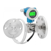
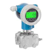
Deltabar S
4 Endress+Hauser
Safety-related parameters In various applications, the operation of pressure or differential pressure transmitters at overpressure
(outside the measuring range, < MWP) or low pressure is not critical.
The state of the processes must be assessed and the various parameters must be taken into
consideration.
• Low pressure or overpressure not dangerous message E727 pressure overrange = Warning
• Low pressure or overpressure dangerous message E727 pressure overrange = Alarm
Depending on the configuration profile selected for the messages (Table ä 14) different
parameters must be considered when assessing the facility:
• Message E727 pressure overrange = Alarm parameter profile A applies
• Message E727 pressure overrange = Warning parameter profile B applies
Parameter profiles A and B depend on the alarm settings and not on the firmware version.
For firmware versions up to and including firmware version 02.20.04, message E727 was set, as a rule,
to "Alarm" for SIL locking with increased security during parameter entry.
With firmware version 02.30.zz and higher, the settings for message E727 remain unchanged,
Table ä 14.
Parameter profile A with message E727 (pressure overrange) configured as an alarm
Parameters according to IEC 61508 Value
Safety functions MIN, MAX, Range
SIL (hardware) • 2 (single-channel),
• 3 (with use of a SIL 3 capable coincidence logic)
SIL (software) 3
Device type B
Operating mode Low demand mode
Safety functions MIN MAX Range
sd
52 FIT 396 FIT 448 FIT
su
440 FIT 440 FIT 440 FIT
dd
396 FIT 52 FIT 0 FIT
du
69 FIT 69 FIT 69 FIT
tot
1)
1) According to Siemens SN29500. This value takes into account all failure types.
1194 FIT
MTBF
tot
)
96 years
SFF 92.8 %
PFD
avg
for T
1
= 1 year (single-channel)
2)
2) If the average temperature during continuous operation is in the region of +50 °C (+122 °F), a factor of 1.3
should be taken into account.
3.02 × 10
-04
Diagnostic test interval
3)
3) During this time, all diagnostic functions are executed at least once.
5 min (RAM, ROM, ...), 1 s (Measurement)
Fault reaction time
4)
4) Time between fault detection and fault reaction.
5 min (RAM, ROM, …), 10 s (Measurement)
Settling time
5)
5) Step response time as per DIN EN 61298-2.
Technical Information TI00382P/00/EN,
"Dead time, time constant (T
)" section

 Loading...