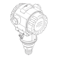
Repair and error handling Deltapilot S FMB70
30 Endress+Hauser
2. Compare displayed pressure measured value with applied pressure and check current
output. Appropriate procedures, measuring equipment and references must be used
for this test. For the lower range value (4 mA value) and upper range value (20 mA
value), compare the applied pressure with the measured pressure. If the measured
pressure differs from the pressure applied to the device, the reference pressure
present must be reassigned to the 4 mA value and the 20 mA value.
For the 4 mA value, see the corresponding Operating Instructions (BA), Description of
Device Functions
• For pressure measurement: SET LRV (245) and GET LRV (309)
• For level measurement: SET LRV (013) ("Level easy pressure" level selection)
For the 20 mA value, see the corresponding Operating Instructions (BA), Description of
Device Functions
• For pressure measurement: SET URV (246) and GET URV (310)
• For level measurement: SET URV (012) ("Level easy pressure" level selection)
Compare the displayed pressure measured value with the applied pressure again and check
the current output. If there are any deviations, contact Endress+Hauser Service.
‣
Carry out steps 5 to 7 of test sequence A.
This check detects 99 % of the dangerous undetected failures.
NOTICE
Regarding test sequence B, Step 2: After this procedure, the current value is output
correctly. The displayed value, e.g. on the local display, and the digital value via HART
may differ from the actual pressure applied.
‣
If the display value and digital value are also to be corrected, please contact Endress
+Hauser Service
6.3 Verification criterion
If one of the test criteria from the test sequences described above is not fulfilled, the
device may no longer be used as part of a safety instrumented system.
• The purpose of proof-testing is to detect dangerous undetected device failures (λ
DU
).
• This test does not cover the impact of systematic faults on the safety function, which
must be assessed separately.
• Systematic faults can be caused, for example, by process material properties, operating
conditions, build-up or corrosion.
• As part of the visual inspection, for example, ensure that all of the seals and cable
entries provide adequate sealing and that the device is not visibly damaged.
7 Repair and error handling
7.1 Maintenance
Maintenance instructions and instructions regarding recalibration may be found in the
Operating Instructions pertaining to the device.
Alternative monitoring measures must be taken to ensure process safety during
configuration, proof-testing and maintenance work on the device.
7.2 Repair
Repair means restoring functional integrity by replacing defective components.
 Loading...


