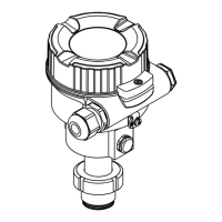
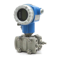
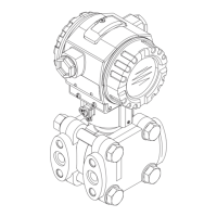
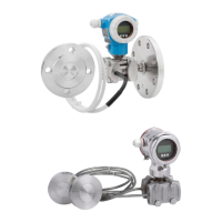
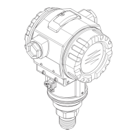
Deltapilot S FMB70 Design
Endress+Hauser 9
3.3.1 Safety-related output signal
The device's safety-related signal is the 4 to 20 mA analog output signal as per NAMUR
NE43. All safety measures refer to this signal exclusively. The device additionally
communicates for information only via HART and contains all HART features with
additional device information. HART communication is not part of the safety function. The
behavior of the output current in the event of a fault depends on the settings for the
alarms and warnings. The safety-related output signal is fed to a downstream logic unit,
e.g. a programmable logic controller or a limit signal transmitter, where it is monitored to
determine whether:
• it exceeds and/or drops below a predefined limit value
• a fault has occurred, e.g. failure current (≤3.6 mA, ≥21.0 mA, signal cable open circuit or
short-circuit).
NOTICE
In an alarm condition
‣
Ensure that the equipment under control achieves or maintains a safe state.
The following dangerous undetected failures can occur in the devices:
• An incorrect output signal that deviates from the real measured value by more than 1 %,
but is still in the 4 to 20 mA or 3.8 to 20.5 mA range
• A settling time that is delayed by more than the specified settling time plus tolerance
For fault monitoring, the logic unit must be able to detect both HI alarms (≥21 mA) and LO
alarms (≤3.6 mA).
The transmitter output is not safety-oriented during the following activities:
• Configuration changes
• Multidrop
• with SW version < 02.20 if the "Bus address (345)" parameter is set to ≠ "0".
• with SW version ≥ 02.20 if the "Current mode (052)" parameter is set to "Fixed" (local
display and FieldCare) or "Disabled" (HART handheld terminal).
• Simulation
• Proof testing
Alternative monitoring measures must be taken to ensure process safety during
configuration, proof-testing and maintenance work on the device.
3.3.2 Redundant configuration of multiple sensors
With redundant configuration with HFT = 1 (e.g. 1oo2 or 2oo3 architecture), the device
meets the requirements for SIL 3.
The common cause factors ß and ß
D
indicated in the table below are minimum values for
the device. These values should be used when calculating the failure probability of
redundantly connected devices according to IEC 61508-6. The plant-specific assessment
can return higher values depending on the particular installation and the use of other
components (e.g. Ex barrier).
Minimum value ß with homogeneous redundant use 5 %
Minimum value ß
D
with homogeneous redundant use 2 %
3.4 Basic conditions for use in safety-related applications
The measuring system must be used correctly for the specific application, taking into
account the medium properties and ambient conditions. Carefully follow instructions
pertaining to critical process situations and installation conditions from the Operating
Instructions. The application-specific limits must be observed. The specifications in the
Operating Instructions and the Technical Information must not be exceeded.
 Loading...


