Appendix Deltapilot S FMB70
32 Endress+Hauser
8 Appendix
8.1 Structure of the measuring system
8.1.1 System components
A0028746
1 PLC (programmable logic controller)
2 2 transmitter power supply units, e.g. RN221N (with communication resistor)
3 Connection for Commubox FXA191, FXA195 and Field Communicator
4 HART handheld terminal, e.g. Field Communicator
5 Computer with operating tool
6 Commubox FXA191 (RS232) or FXA195 (USB), FXA291
7 Field Xpert
8 VIATOR Bluetooth modem with connecting cable
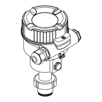
9 Transmitter
An analog signal (4 to 20 mA) that is in proportion to the pressure is generated in the
transmitter. This is sent to a downstream logic unit (e.g. PLC, limit signal transmitter, etc.)
where it is monitored to determine whether it is below or above a specified limit value.
For fault monitoring, the logic unit must be able to detect both HI alarms (≥ 21.0 mA) and
LO alarms (≤ 3.6 mA).
8.1.2 Description of use as a protective system
The device is used for the following measuring tasks:
• Level, volume or mass measurements in liquids
• Pressure measurement in liquids, gases and paste-like media in all areas of process
engineering, process measurement technology, pharmaceutics and the food industry
8.1.3 Installation conditions
The installation conditions for various measurements are described in the Technical
Information for the device.
Correct installation is a prerequisite for safe operation of the device.
8.1.4 Measurement function
The measuring principle and the measurement functions are described in the Technical
Information for the device

 Loading...