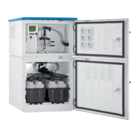
Installation Liquistation CSF33
18 Endress+Hauser
Requirements for the sampling point:
• Do not connect the suction line to pressurized systems.
• Use the suction filter to impede coarse and abrasive solids and solids which can cause
clogging.
• Immerse the suction line in the direction of flow.
• Take the sample at a representative point (turbulent flow, not directly at the bottom of
the channel).
Useful sampling accessories
Suction filter:
Impedes coarser solids and solids which can cause clogging.
5.1.5 Connection for sample intake on version with sample pump
• Maximum suction height:
• Vacuum pump: Standard 6 m (20 ft)
• Peristaltic pump: standard 8 m (26 ft)
• Maximum hose length: 30 m (98 ft)
• Hose connection diameter
• Vacuum pump: 13 mm (1/2")
• Peristaltic pump: internal diameter of 10 mm (3/8")
• Intake speed:
> 0.6 m/s (> 1.9 ft/s) for 10 mm (3/8") ID, as per Ö 5893, US EPA
> 0.5 m/s (> 1.6 ft/s) for ≤ 13 mm (1/2") ID, in accordance with EN 25667, ISO 5667
Note the following when erecting the device:
• Always route the suction line so that it slopes upwards from the sampling point to the
sampler.
• The sampler must be located above the sampling point.
• Avoid siphoning effects in the suction line.
Requirements for the sampling point:
• Do not connect the suction line to pressurized systems.
• Use the suction filter to impede coarse and abrasive solids and solids which can cause
clogging.
• Immerse the suction line in the direction of flow.
• Take the sample at a representative point (turbulent flow, not directly at the bottom of
the channel).
Useful sampling accessories
Suction filter:
Impedes coarser solids and solids which can cause clogging.
5.2 Installation
5.2.1 Connecting the suction line at the side on version with pump
1. When installing the device, take the installation conditions into account.
2. Route the suction line from the sampling point to the device.
3. Screw the suction line onto the device's hose connection.
5.2.2 Connecting the suction line from the bottom on version with
pump
If the suction line is connected from below, the suction line is routed upwards behind the
rear panel of the sample compartment. First remove the rear panel of the dosing
compartment and sample compartment as described in the "Electrical connection" section.
1. Remove the drain plug from the hose gland located at the back of the device base.

 Loading...