Micropilot FMR56, FMR57
Endress+Hauser 37
The beam angle is defined as the angle α where the energy density of the radar waves reaches half
the value of the maximum energy density (3dB width). Microwaves are also emitted outside the
signal beam and can be reflected off interfering installations.
Beam diameter W as a function of beam angle α and distance D.
Antenna horn 100 mm (4 in), α 8 °
W = D × 0.14
Antenna horn 200 mm (8 in), α 10 °
W = D × 0.18
Parabolic antenna 200 mm (8 in), α 4 °
W = D × 0.07
Parabolic antenna 250 mm (10 in), α 3.5 °
W = D × 0.06
Process conditions
• The measuring range begins where the beam hits the bottom. Levels below this point cannot be
detected, particularly in the case of conical outlets. The maximum measuring range in such
applications can be increased by using an alignment unit.
• In the case of media with a low ε
r
= 1.5 to 2.5, the tank bottom may be visible through the medium
at low levels. To ensure the necessary level of accuracy, we recommend positioning the zero point
at a distance C above the floor (see Figure) in these applications.
The dielectric constants (ε
r
values) for many key media used in industry are provided in the DC
Manual (CP00019F) and in Endress+Hauser's "DC Values App" (available for Android and iOS).
• In principle it is possible to measure up to the tip of the antenna with the Micropilot. However, due
to considerations regarding abrasion and build-up, and depending on the orientation of the
product (angle of repose), the end of the measuring range should be at a distance A (see Figure)
from the tip of the antenna. If required, and if conditions are met (high ε
r
value, flat angle of
repose), shorter distances can be achieved.
A0042712
A 400 mm (15.7 in)
C 50 to 150 mm (1.97 to 5.91 in)
Free-space installation in
vessel
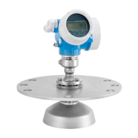
Horn antenna with slip-on flange (FMR56)
Alignment
If using the Micropilot with a slip-on flange in explosion-hazardous areas, observe all the
specifications in the relevant Safety Instructions (XA).
 Loading...


