Micropilot FMR56, FMR57
Endress+Hauser 39
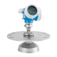
Horn antenna with mounting bracket (FMR56)
A0016865
21 Mounting the horn antenna with a mounting bracket
Using the mounting bracket, position the antenna so that it is perpendicular to the product surface.
NOTICE
There is no conductive connection between the mounting bracket and transmitter housing.
Risk of electrostatic charge.
‣
Integrate the mounting bracket in the local potential equalization system.
Horn antenna (FMR57)
Alignment
• Ideally, the horn antenna should be installed vertically. To avoid interference reflections or for
optimum alignment in the vessel, the Micropilot can be swiveled by 15° in all directions with the
optional alignment device.
• A marking is provided on the gland to aid the alignment. This marking must be aligned towards
the tank wall as much as possible.
A0019434
Depending on the device version the marking may be a circle or two parallel lines.
Information concerning nozzles
The horn antenna should project out of the nozzle. If this is not possible for mechanical reasons,
larger nozzle heights can be accepted.
 Loading...


