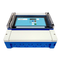
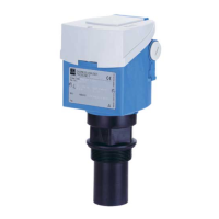
Electrical connection Prosonic S FMU90 PROFIBUS DP
24 Endress+Hauser
Terminal areas
• Basic terminal area (A)
Found on all device versions
• Terminal area for additional inputs and outputs (B)
Found on the following device versions:
• FMU90 - *****2******
• FMU90 - *******2****
• Terminal area for relays (C)
Found on the following device versions:
• FMU90 - ******3*****
• FMU90 - ******6*****
• Terminal area for switch inputs and temperature inputs (D)
Found on the following device version:
FMU90 - ********B***
• Terminal area for PROFIBUS DP (E)
Found on the following device version:
FMU90 - *******3****
FDU-
Sensor
0/4...20mA
1
42
41
Relay
55
52
54
51
53
50
3
Address
Term.
DP
off
on
off
on
SW
HW
1
2
3
4
5
6
7
8
1
2
3
4
A(N)
66
B(P)
65
Display
POWER
HART
0/4…20mA
Sync
Fuse
I
1
FDU-
Sensor
RD
11
BK
10
YE
9
40
39
5
4
67
8
1
1
Service
Relay
32
1
A
B
C
E
2
58
5756
4
61
6059
5
64
6362
6
RD
11
BK
10
YE
9
2
RD
14
BK
13
YE
12
I
2
FDU-
Sensor
DigIn
76
73
75
72
74
71
D
79
7877
82
8180
2
1
3
4
85
8483
Temp.
A0034899
21 Terminals of Prosonic S (the terminals shown in gray are not available in every device version)
A Basic terminal area
B Optional terminal area for two sensors
C Optional terminal area for up to five relays
D Optional terminal area for up to four external switches and one external temperature sensor
E Optional terminal area for PROFIBUS DP
The relay switching states depicted above refer to the de-energized state.
Terminals for power supply (AC version)
Terminal area A
• Terminal 1: L (90 to 253 V
AC
)
• Terminal 2: N
• Terminal 3: potential equalization
• Fuse: 400 mA T

 Loading...


