Operating Instructions Raman Rxn2
12 Endress+Hauser
3.3.2 Rear panel
On the rear panel of the instrument are standard input/output (I/O) ports. These include touchscreen, USB, Ethernet,
serial, and video ports.
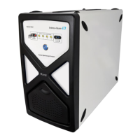
Figure 2. Rear external circuit input/output panel of a Raman Rxn embedded analyzer
RS-485 serial port, half-duplex. Provides automation data via Modbus remote terminal
unit (RTU). Port settings configurable in Raman RunTime.
3.3.3 Rear panel: Rxn2 single-channel and four-channel configurations
All normal system input/output (I/O) is located at the rear of the base unit. This includes:
• EO fiber connector/electrical connections for up to four remotely installed probes for the four-channel Raman
Rxn2 analyzer (single-channel analyzers have only one probe connection). The electrical connection contained
within the fiber optics is an intrinsically safe interlock loop which will turn off the laser in case of fiber breakage.
• Four remote interlock connections for the four-channel Raman Rxn2 analyzer (only one for the single-channel
configuration), each intrinsically safe and in series with the fiber breakage detection loops described in previous
bullet.
• Two TCP/IP Ethernet ports for OPC and Modbus automation as well as remote control
• One serial RS-485 port for Modbus automation.
• One mini DisplayPort for local display (if needed)
• Two USB 2.0 Type A ports, one for local touchscreen (if needed) and one reserved for future use
• AC power inlet, C13 plug required. See Specifications → .
Handle probes and cables with care.
Fiber cables should NOT be kinked and should be routed to maintain the minimum bend radius of 152.4 mm
(6 in).
Permanent damage to the cables may result if they are bent beyond the minimum radius.