18
Enertech Global IOM, XT Models
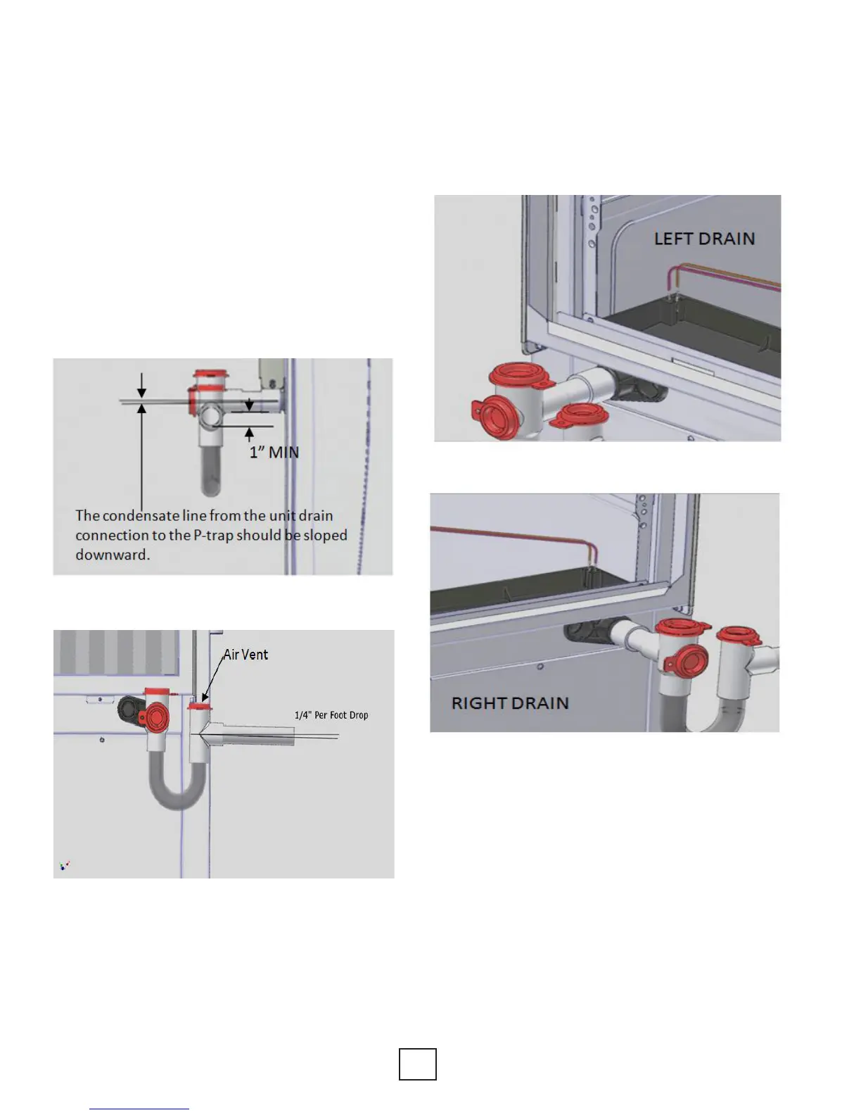
Condensation Drain Connection
Connect the EZ-Trap to the equipment condensate
drain connection as shown in gures 9a through 9d.
The condensate line must be trapped a minimum
of 1.0” as shown on diagram. The condensate line
should be pitched away from the unit a minimum
of 1/4” per foot. The condensate line from the unit
drain connection to the P-trap should be sloped
downward. For moreinformation on installing EZ-Trap,
see installationsheet that comes with the EZ-Trap Kit.
Always install the air vent after the trap.
Note: Connect the drain through the trap to the
condensation drain system in conformance
to local plumbing codes.
Part Number Description
ACDT1A EZ-Trap ¾” Kit
ACDT2A EZ-Trap 1” Kit
Figure 9a: Condensation Drain Connection
Figure 9d: Right Overow Sensor Connection
Figure 9c: Left Overow Sensor Connection
Note: Make Sure the condensate overow sensor is
mounted to the side closest to the drain being used
as shown in gures 9c and 9d below.
Section 5: Unit Piping Installation
Figure 9b: Condensation Drain Drop