38
Enertech Global IOM, XT Models
Safety Controls
The control receives separate signals for high
pressure, low pressure, low water ow, and
condensate overow faults. Upon a continuous
30-second measurement of the fault (immediate for
high pressure), compressor operation is suspended
(see Fault Retry below), and the appropriate LED
ashes. Once the unit is locked out (see Fault Retry
below), an output (terminal “L”) is made available
to a fault LED at the thermostat.
Low Pressure: If the low pressure switch is open for
30 continuous seconds, the compressor operation
will be interrupted, and the control will go into fault
retry mode. At startup, the low pressure switch is not
monitored for 90 seconds to avoid nuisance faults.
High Pressure: If the high pressure switch opens, the
compressor operation will be interrupted, and the
control will go into fault retry mode. There is no delay
from the time the switch opens and the board goes
into fault retry mode. There is also no delay of switch
monitoring at startup.
Flow Switch: If the ow switch is open for 30
continuous seconds, the compressor operation will
be interrupted, and the control will go into fault retry
mode. At startup, the ow switch is not monitored
for 30 seconds to avoid nuisance faults.
Condensate Overow: If water touches the
condensate overow sensor for 30 continuous
seconds, the compressor operation will be
interrupted, and the control will go into fault retry
mode. There is no delay of switch monitoring at
startup.
Fault Retry
All faults are retried twice before nally locking the
unit out. The fault retry feature is designed to prevent
nuisance service calls. There is an anti-short cycle
(ASC) period (5 min.) between fault retries. On the
third fault within 30 minutes, the board will go into
lockout mode and the “Call For Service” indicator
on the thermostat will illuminate.
Intelligent Lockout Reset
If the thermostat is powered off then back on (soft
reset), the board will reset and the last fault will be
stored in memory for ease of troubleshooting. If
power is interrupted to the board, the fault memory
will be cleared.
Over/Under Voltage Protection
The lockout board protects the compressor from
operating when an over/under voltage condition
exists. The control monitors secondary voltage
(24VAC) to determine if an over/under voltage
condition is occurring on the primary side of the
transformer. For example, if the secondary voltage
is 18VAC, the primary voltage for a 240V unit would
be approximately 180V, which is below the minimum
voltage (197V) recommended by the compressor
manufacturer. Under voltage (<18VAC) causes the
compressor to disengage and restart when the
voltage returns to >20VAC. Over voltage (>31VAC)
causes the compressor to disengage and restart
when the voltage returns to <29VAC.
When an O/U Voltage condition occurs, the board
will initiate a fault, shut down the compressor, and
start the ve minute ASC period. All four fault LEDs
will ash (HP + LP + FS + CO) and the thermostat
“Call For Service” indicator will be illuminated. This
feature is self-resetting. If voltage returns to normal
range normal operation will resume if/when the ASC
period is over (except if in lockout mode). If voltage
is still out of range at the end of the ASC period the
control will execute a Fault Retry. On the third fault
within 30 minutes, the board will go into lockout
mode and illuminate the “Call For Service” indicator.
When normal operation is restored the four fault
LED’s will stop ashing and the “Call For Service”
indicator will turn off.
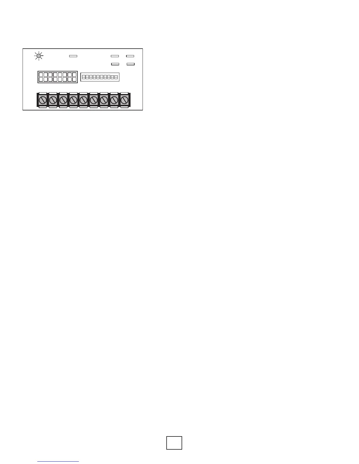
Section 9: Controls
O/B Y1 G W1 R ODD W2 Y2 C
W1
COM
24VAC
COM2
XFMR
SEC
CFM
Figure 13: ECM Board Layout