26
Enertech Global IOM, XT Models
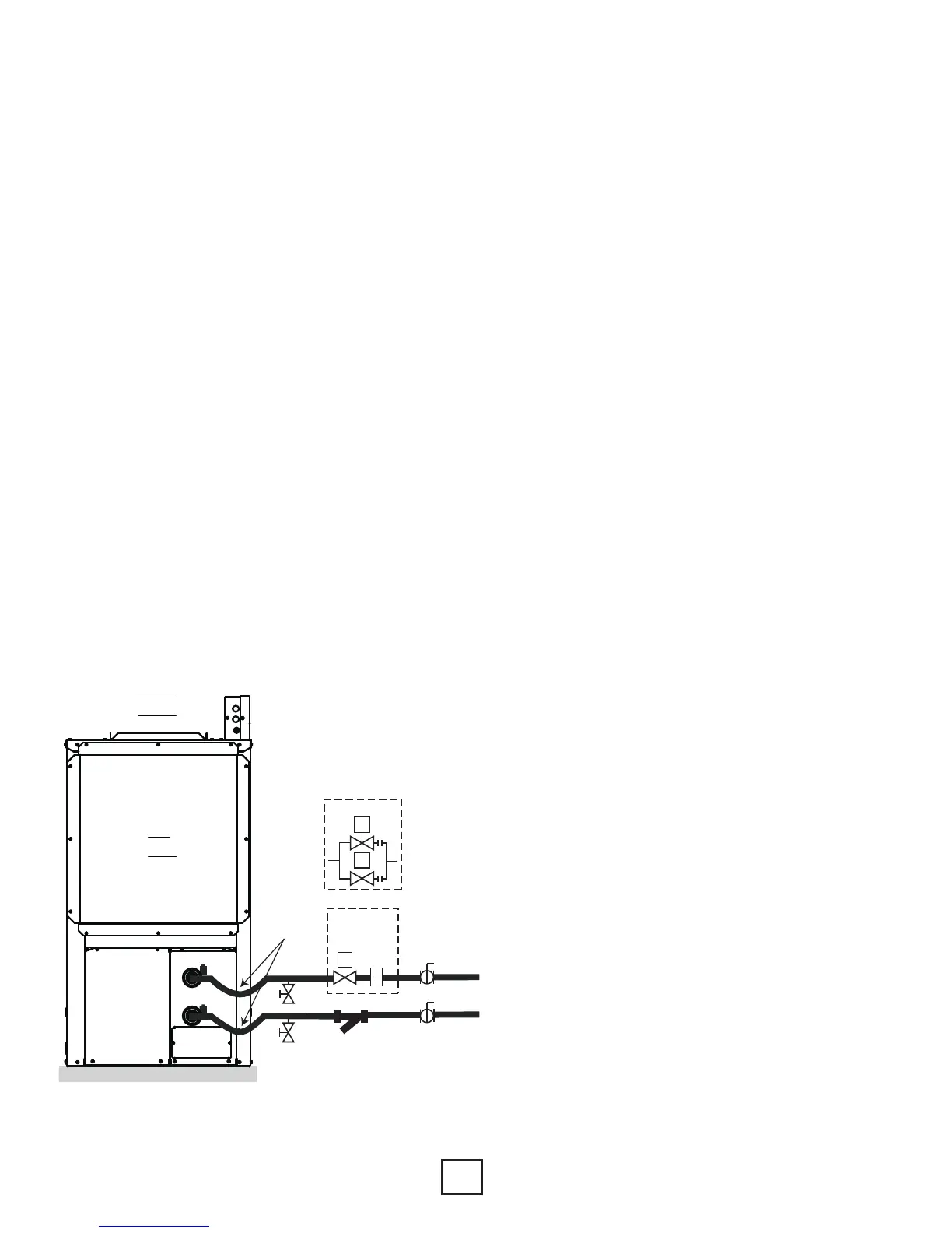
Open Loop Piping and Connections
Placement of the components for an open loop
system are important when considering water quality
and long term maintenance. The water solenoid
valve should always be placed on the outlet of the
heat pump, which will keep the heat exchanger
under pressure when the unit is not operating. If the
heat exchanger is under pressure, minerals will stay in
suspension. Water solenoid valves are also designed
to close against the pressure, not with the pressure.
Otherwise, they tend to be noisy when closing.
A ow regulator should be placed after the
water solenoid valve. Always check the product
specication catalog for proper ow rate. A
calculation must be made to determine the ow
rate, so that the leaving water temperature does not
have the possibility of freezing.
Other necessary components include a strainer,
boiler drains for heat exchanger ushing, P/T ports
and ball valves. Ball valves allow the water to be
shut off for service, and also help when velocity
noise is noticeable through the ow regulator.
Spreading some of the pressure drop across the ball
valves will lessen the
velocity noise. Always double check ow rate at the
P/T ports to make sure the ball valve adjustments
have not lowered water ow too much, and
essentially taken the ow regulator out of the
equation. It’s a good idea to remove the ball valve
handles once the system is completed to avoid
nuisance service calls.
Hose kits are optional, but make for an easier
installation, since the P/T ports and connections are
included. The hose also helps to isolate the heat
pump from the piping system.
Since the heat pump can operate at lower
waterow on rst stage, two stage units typically
include two water solenoid valves to save water.
The ow regulators should be sized so that when
one valve is open the unit operates at rst stage
ow rate, and when both valves are open, the unit
operates at full load ow rate. For example, a 4 ton
unit needs approximately 4 GPM on rst stage, and
approximately 7 GPM at full load. The ow regulator
after the rst valve should be 4 GPM, and the ow
regulator after the second valve should be 3 GPM.
When both valves are open, the unit will operate at
7 GPM.
The drawings show typical components, wiring and
connection points. Electrical connections are found
at the control box terminal strips.
Figure 5: Open Loop Piping Example
LEFT
VIEW
air
coil
Non-Pressurized
Flow Center
P/T Ports
Source Out
Source In
P/T Ports
*Hose
Kits
Equipment Pad
2” Polyethylene Foam
Boiler
Drains
(2 required)
S
Single Stage
Units
Ball Valve
(2 required)
S
S
Two Stage Units
Strainer
(optional)
OR
**Flow
Regulator
From
Loop
Field
To
Loop
Field
Flush
Valve
*Hose kit is used for piping isolation, and includes ttings for P/T ports.
**See product specifications for flow rates.
Note: All XT models are
two-stage units.
Two-Stage solenoid example
is optional for all sizes. It is not
recommended for 3 ton and
smaller. Use single solenoid
and ow regulator.
Section 5: Unit Piping Installation