Step 3: Position the Enphase Engage™ Cable
The Engage Cable is a continuous length of outdoor rated cable with integrated connectors for
microinverters. These connectors are preinstalled along the Engage Cable at intervals to accommodate
PV module widths. The microinverters plug directly into the connectors, and the Engage Cable is
terminated into the junction box that feeds electricity back to the system AC disconnect. For more
information, see “Engage Cable Planning and Ordering” on page 30.
NOTE: Make sure you are using the correct cable type. Use 400 Vac Engage Cable at sites with three-
phase service, or use 230 Vac Engage Cable at sites with single-phase service. Check the labelling on the
drop connectors to verify the voltage type.
a. Plan the cable route so that the drop connectors on the Engage Cable align with each PV
module. Allow extra length for slack, cable turns and any obstructions.
b. Measure the path of the AC branch circuit and cut a length of Engage Cable to meet your
needs.
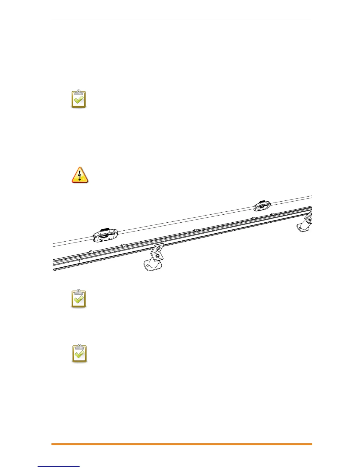
c. Lay the Engage Cable along the route it will travel, positioning the connectors so that they
align with the PV modules.
WARNING: Risk of fire. Plan the AC branches so that they do not exceed the maximum number of
microinverters in an AC branch circuit as listed on page 9 of this manual. You must protect each microinverter
AC branch circuit with a 20A maximum breaker.
NOTE: Many PV modules have a central stiffening brace. In these cases, do not position the connector and
microinverter at the exact centre of the PV module. Instead, position the drop connectors so that the
connectors do not conflict with the braces.
d. PV module widths vary by manufacturer. On the Engage Cable, connectors are spaced at
intervals to allow for the widest PV modules compatible with Enphase Microinverters. If
narrower PV modules are used, it may be necessary to account for excess cable by looping
the cable at suitable intervals.
NOTE: When looping the Engage Cable, do not form loops smaller than 12 cm in diameter.