Step 10: Complete the Installation Map
The Enphase Installation Map is a diagrammatic representation of the physical location of each
microinverter in your PV installation. You will create the virtual array in Enlighten from this map. Use the
blank map on page 39 to record microinverter placement for the system, or provide your own layout if a
larger or more intricate installation map is required.
You can build the system map manually, by peeling the serial number labels from the microinverters and
placing the labels on the installation map, or you can use the scanning tool feature from the Enphase
Installer Toolkit to easily build and configure a system. Refer to http://enphase.com/installer-toolkit/ for
more information.
To manually build the Installation Map:
Each Enphase Microinverter has a removable serial number label located on the mounting
plate. Peel the removable serial number label from each Enphase Microinverter and affix it to
the respective location on the Enphase installation map (see map on page 39). Remember
to keep a copy of the installation map for your records.
Draw a top-down view of the array using the Array Map template. Make sure to leave
enough room to place the serial number stickers.
When installing the microinverters, remove the serial number labels located next to the DC
input cables and place them in the correct order on your drawing of the system. Remember
to keep a copy of the installation map for your records.
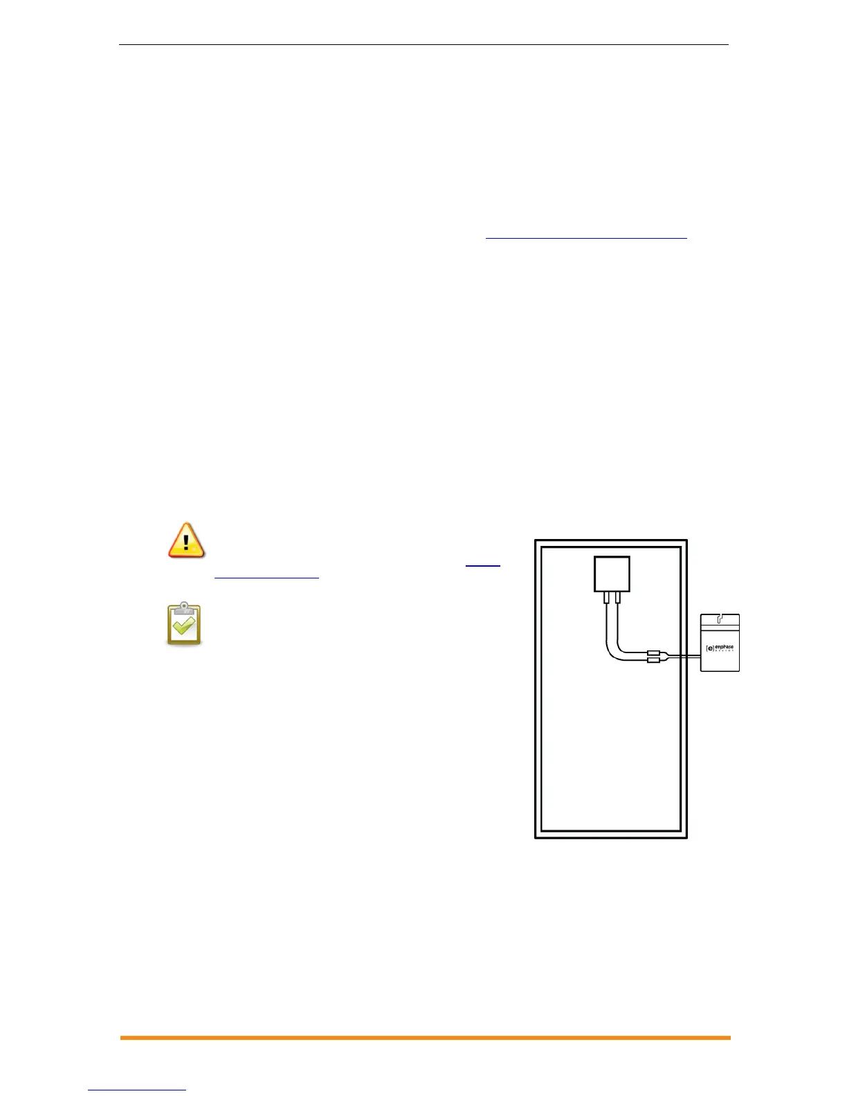
Step 11: Connect the PV Modules
WARNING: Risk of equipment damage. Be sure to verify the
voltage and current specifications of your PV module match those
of the microinverter. For more information, refer to our module
compatibility calculator.
NOTE: Completely install all microinverters and all system AC
connections prior to installing the PV modules.
a. Mount the PV modules above the microinverters.
b. Mate the microinverters and PV modules as required.
Repeat for all remaining PV modules using one
microinverter for each PV module.
The status LED on the underside of each microinverter
lights green six seconds after DC power is applied. It
remains lit solid for two minutes, followed by six green
blinks. After that, red blinks indicate that no grid is
present. This is because the AC breaker is not turned on
yet.