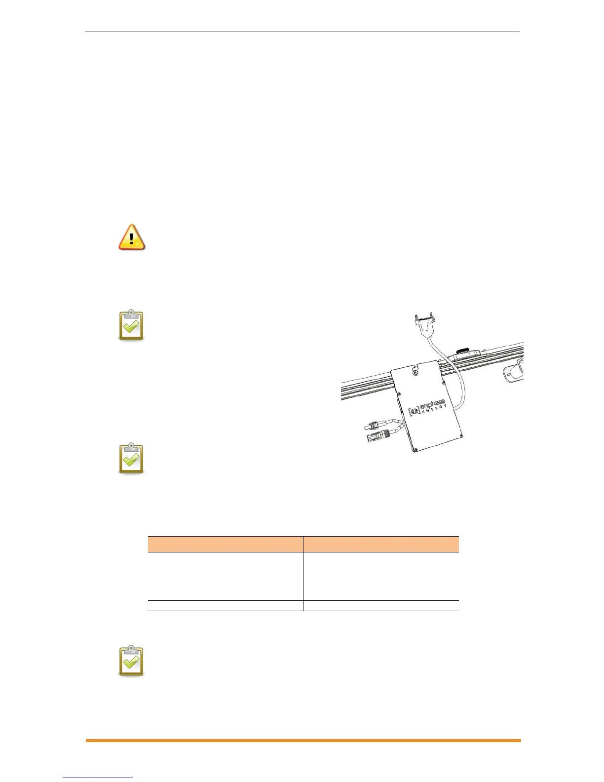
Step 5: Attach the Microinverters to the Mounting Rail
a. Mark the approximate centres of each PV module on the mounting rail.
b. Evaluate the location of the microinverter with respect to the PV module DC junction box or
any other obstructions.
c. Ensure that the microinverter does not interfere with the PV module frame or stiffening
braces.
d. Ensure that the connector from the microinverter can easily reach the connector on the
Engage Cable.
e. Allow a minimum of 1.9 cm (0.75 inches) between the roof and the bottom of the
microinverter. Also allow 1.3 cm (0.50 inches) between the back of the PV module and the
top of the microinverter.
WARNING: Risk of equipment damage. You must install the microinverter under the module, out of rain and
sun. Do not mount the microinverter in a position that allows long-term exposure to direct sunlight or in a
vertical orientation that allows water to collect in the DC connector recess. Do not install the microinverter
black-side up or vertically, with the DC connectors facing up.
f. Mount one microinverter at each location using suitable hardware. The indicator light on the
underside of the microinverter will be facing the roof.
NOTE: Installing the microinverter black side up or
vertically, with the DC connectors facing up, is not
permitted.
g. Torque the microinverter fasteners to the
values shown. Do not over torque.
6 mm (1/4”) mounting hardware – 5 Nm
(45 to 50 in-lbs)
8 mm (5/16”) mounting hardware – 9 Nm
(80 to 85 in-lbs)
NOTE: Using a power screwdriver to
tighten the screws is not recommended
due to the risk of thread galling.
h. If you are using an earth bonding conductor to bond the microinverter chassis, attach the
bonding conductor to the microinverter bonding screw.
i. Torque the bonding screw as follows: