M-Series Microinverter Installation and Operation
2016 Enphase Energy. All rights reserved. 141-00024 Rev 02b
Planning for Microinverter Installation
Enphase Microinverters are compatible with many PV modules and install quickly and easily. They
include integrated DC and AC cables and connectors. The DC connectors attach to the PV module, while
the AC connector attaches directly to the Engage Cable. No additional cabling is needed.
The Engage Cable is available in multiple connector spacing options and two voltage types to meet
varying site requirements. For Engage Cable ordering information, see “Engage Cable Planning and
Ordering” on page 30.
WARNING: Be aware that installation of this equipment includes risk of electric shock. Normally earthed
conductors may be unearthed and energised when an earth fault is indicated.
Compatibility and Capacity
The Enphase M215 and M250 Microinverters are electrically compatible with many PV modules. For
more information, see Technical Data on page 33 of this manual.
Refer to the Enphase website (http://www.enphase.com/support) for a list of electrically compatible PV
modules and approved mounting rail systems. To ensure mechanical compatibility, be sure to order
the correct connector type for both microinverter and PV module from your distributor.
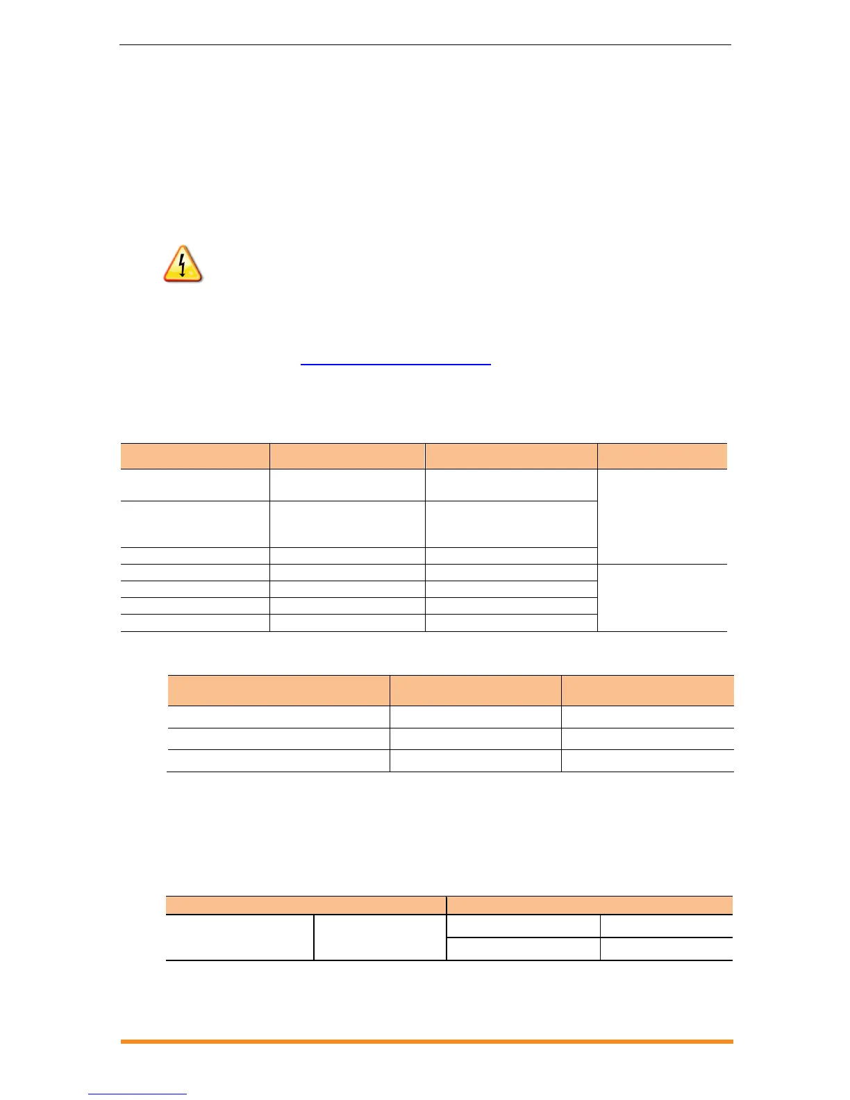
Compatibility
* To centre-feed a branch, divide the circuit into two sub-branch circuits protected by a single overcurrent
protection device (OCPD).
Utility Service Requirements
The Enphase Microinverter works with single phase or three phase 230 Vac service. Measure AC line voltage at the electrical utility
connection to confirm that it is within the ranges shown: