Epec CAN Module Family
2024 CONTROL MODULE
20 / 34
07.10.2010
2024G08,G18 / MAN000185
Epec Oy reserves all rights for improvements without prior notice
Epec Oy Postiosoite/Postal address Puhelin/Phone Fax Internet
Tiedekatu 6 PL/P.O.Box 194 +358-(0)20-7608 111 +358-(0)20-7608 110 www.epec.fi
FIN-60320 Seinäjoki FIN-60101 Seinäjoki, Finland
Electrical Characteristics
Symbol Parameter Conditions Min Max Units
R
I
Input Resistance
V
I
greater than 4,3 V (Note 1) 9,0 11
k
Referenced to 1,3 V;
V
I
less than 4,3 V (Note 1)
6,2 7,6
kΩ
V
IH
Input High Voltage 4,8 30 V
V
IL
Input Low Voltage -0,5 4,2 V
f
I
Input Frequency
(frequency
measurement and
pulse counting)
(Note 2, 3, 6) 5 kHz
Sum of the frequencies of all the
pins (Note 2, 3, 6)
40 kHz
Input Frequency
(normal inputs)
t
C
=10 ms (Note 3, 4, 5, 7) 12 Hz
Variable t
C
(Note 3, 5, 7) 1/8t
C
t
I
Input Pulse Width
Note 3, 6 50 µs
t
C
=10 ms (Note 3, 4, 5, 7) 40 ms
Variable t
C
(Note 3, 5, 7) 4t
C
C
I
Input Capacitance 0,8 47 nF
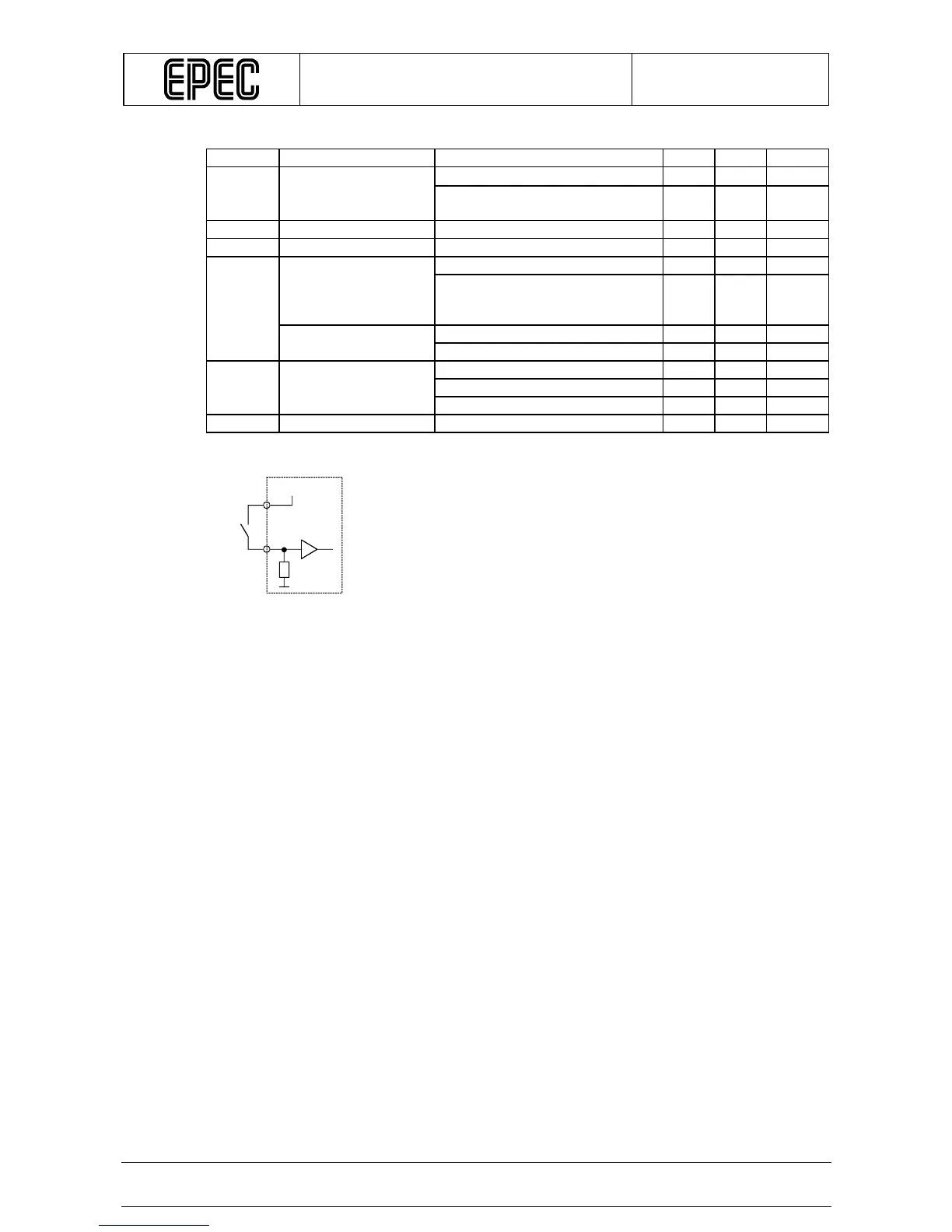
Connection Principle
Note 1: With input voltages below 4,3 V it seems like the internal input resistance was
connected to a 1,3 V voltage source
Note 2: All conditions must be respected. Even if some of the inputs were not used for
frequency measurement or pulse counting, these conditions must nevertheless be
respected regarding those inputs too. Otherwise operation of other inputs may be
interfered
Note 3: Violating this rating may lead to system not recognizing all input state transitions
Note 4: These parameters depend on software cycle time
Note 5: t
C
denotes software cycle time
Note 6: Applies to inputs used for frequency measurement and pulse counting. Violating this
rating may lead to incorrect measurement or counting
Note 7: Applies to inputs used as normal digital inputs. Violating this rating may lead to
application program not noticing all input state transitions
+24V/+12V
Module