Epec CAN Module Family
2024 CONTROL MODULE
25 / 34
07.10.2010
2024G08,G18 / MAN000185
Epec Oy reserves all rights for improvements without prior notice
Epec Oy Postiosoite/Postal address Puhelin/Phone Fax Internet
Tiedekatu 6 PL/P.O.Box 194 +358-(0)20-7608 111 +358-(0)20-7608 110 www.epec.fi
FIN-60320 Seinäjoki FIN-60101 Seinäjoki, Finland
5 BUS CONNECTION
5.1 Bus Connection Pins
The CAN communication pins and the power supply are connected in the module’s AMP8
connector as follows:
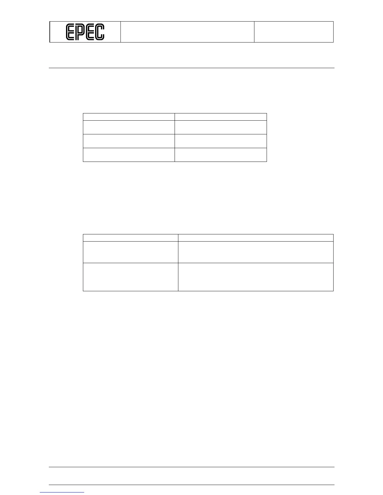
Designation Connector / pin number
CAN1 interface, system interface X4.2 (CAN H)
X4.6 (CAN L)
CAN2 interface, user
programmable communication
X4.7 (CAN H)
X4.8 (CAN L)
Factory use only,
this pin must be left open
X3.15
5.2 CAN Interface
Higher layer protocol is user programmable (CAN2) communication. The physical interface of
CAN interface is according to ISO 11898 and CAN 2.0B protocol. The downloading of the
application programs can only be done via CAN1.
The programmability of CANs depends on the used programming environment as described in
the following table:
Programming environment CAN programmability
CoDeSys 2.1
CAN1 is CANopen compatible
• CAN2 is user programmable
• CANopen is not available for CAN2
CoDeSys 2.3
CAN1 and CAN2 are CANopen compatible and user
programmable
• For example CANopen, SAE J1939 or ISOBUS are
available for both CANs.