Epec CAN Module Family
2024 CONTROL MODULE
17 / 34
07.10.2010
2024G08,G18 / MAN000185
Epec Oy reserves all rights for improvements without prior notice
Epec Oy Postiosoite/Postal address Puhelin/Phone Fax Internet
Tiedekatu 6 PL/P.O.Box 194 +358-(0)20-7608 111 +358-(0)20-7608 110 www.epec.fi
FIN-60320 Seinäjoki FIN-60101 Seinäjoki, Finland
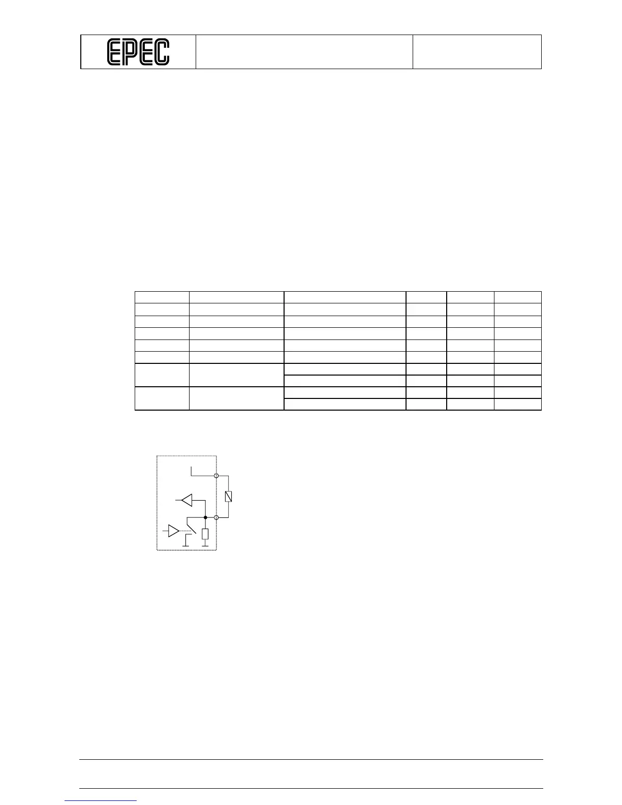
3.6 Digital Input / Digital Output (sinking)
Pins X1.18, X1.21, X2.18, and X2.21 are current sinking outputs. In other words, pins connect
the load to the ground. The application program can also simultaneously monitor the actual
state of the pin. This feature makes it possible to detect open loads and short circuits to the
supply voltage.
In very carefully selected applications a pin of this type can also be used as an input by using
the output state monitoring feature. In those cases, the output functionality of the pin must of
course be kept in off state. It must be taken care in system design that the output unintentionally
switching to on state causes no harm to system.
There are two bit variables associated with each pin of this type in PLCopen programming
environment. The first is one of the QX output bits for controlling the pin as an output. The
second is one of the IX input bits for monitoring the actual state of the output or reading the pin
as an input.
Electrical Characteristics
Symbol Parameter Conditions Min Max Units
R
O
Output Resistance Output On 0,12
Ω
I
O
Output Current Output On 3 A
R
I
Input Resistance Output Off 9 11
k
V
IH
Input High Voltage Output Off 3,0 30 V
V
IL
Input Low Voltage -0,5 1,0 V
f
I
Input frequency
t
C
=10 ms (Note 1, 2, 3) 12 Hz
Variable t
C
(Note 1, 3) 1/8t
C
t
I
Input Pulse Width
t
C
=10 ms (Note 1, 2, 3) 40 ms
Variable t
C
(Note 1, 3) 4t
C
Connection Principle
+24V
Module
Load