Epec CAN Module Family
2024 CONTROL MODULE
10 / 34
07.10.2010
2024G08,G18 / MAN000185
Epec Oy reserves all rights for improvements without prior notice
Epec Oy Postiosoite/Postal address Puhelin/Phone Fax Internet
Tiedekatu 6 PL/P.O.Box 194 +358-(0)20-7608 111 +358-(0)20-7608 110 www.epec.fi
FIN-60320 Seinäjoki FIN-60101 Seinäjoki, Finland
3.2 Digital Input
Pins X1.19, X1.20, X2.19, and X2.20 are ground referenced inputs (DI).
Pins are associated with a bit variable in the IX area in PLCopen programming environment.
The application program will see there a logical zero when the pin is grounded or left open and
a logical one when the pin is connected to a positive voltage source.
Electrical Characteristics
Symbol Parameter Conditions Min Max Units
R
I
Input Resistance
V
I
Greater than 4,3 V (Note 1) 9,0 11
k
Referenced to 1,3 V;
V
I
Less than 4,3 V (Note 1)
6,2 7,6
kΩ
V
IH
Input High Voltage 4,8 30 V
V
IL
Input Low Voltage -0,5 4,2 V
f
I
Input Frequency
t
C
=10 ms (Note 2, 3, 4, 5) 12 Hz
Variable t
C
(Note 2, 3, 5) 1/8t
C
C
I
Input Capacitance 37 57 nF
Note 1: With input voltages below 4,3 V it seems like the internal input resistance was
connected to a 1,3 V voltage source.
Note 2: t
C
denotes software cycle time.
Note 3: Violating this rating may lead to system not recognizing all input state transitions.
Note 4: These parameters depend on software cycle time.
Note 5: Applies to inputs used as normal digital input. Violating this rating may lead to
application program not noticing all input state transitions.
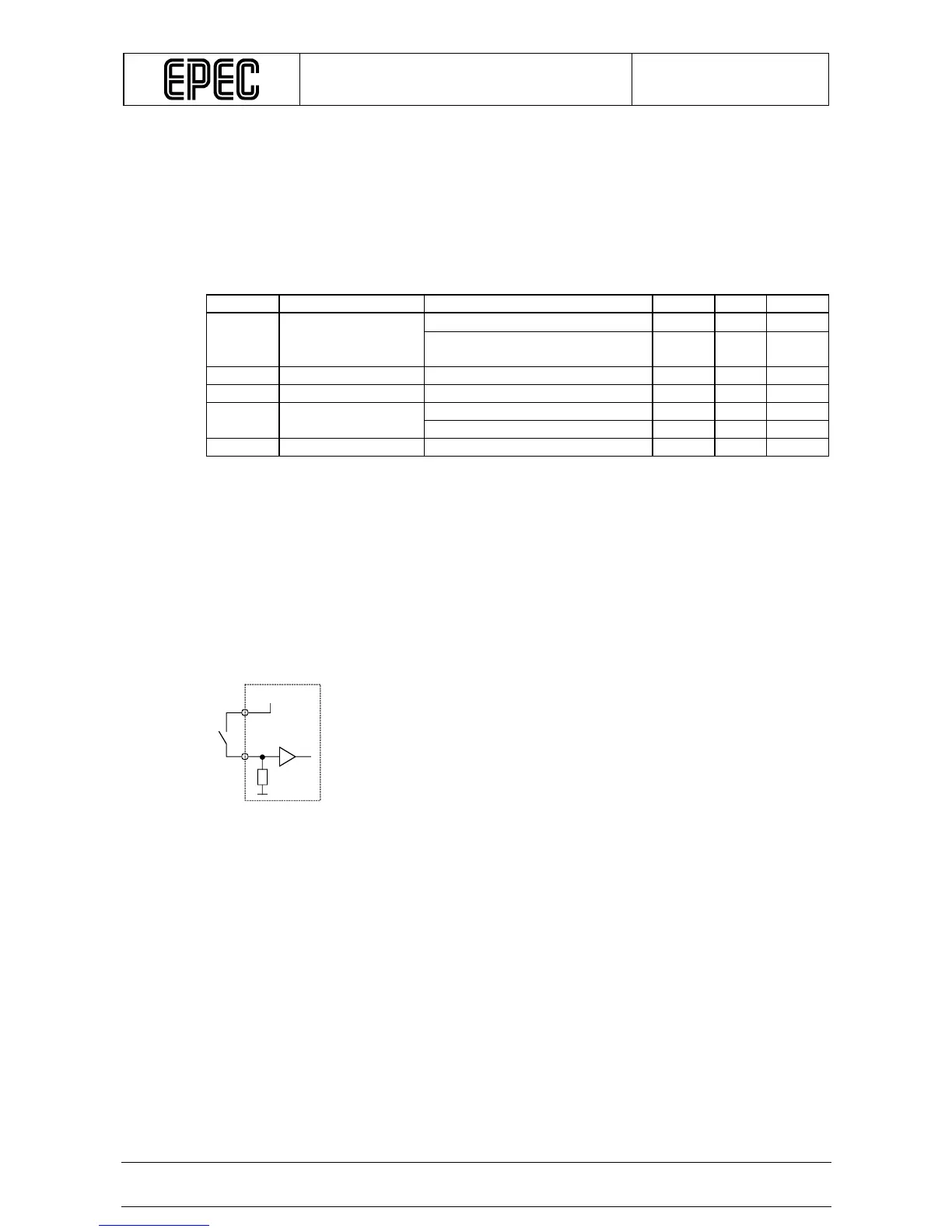
Connection Principle
+24V/+12V
Module