Epec CAN Module Family
2024 CONTROL MODULE
11 / 34
07.10.2010
2024G08,G18 / MAN000185
Epec Oy reserves all rights for improvements without prior notice
Epec Oy Postiosoite/Postal address Puhelin/Phone Fax Internet
Tiedekatu 6 PL/P.O.Box 194 +358-(0)20-7608 111 +358-(0)20-7608 110 www.epec.fi
FIN-60320 Seinäjoki FIN-60101 Seinäjoki, Finland
3.3 Current Measuring Feedback
Pins X1.5, X1.6, X2.3, and X2.4 are normally used as a return path for the loads of PWM
outputs. These kinds of pins have a small shunt resistor connected to ground. The shunt
resistor is used to measure the current flowing through the load. Nothing prevents using these
pins to measure currents from other sources as well.
In PLCopen programming environment, there is a word variable in IW area associated with each
pin from where the software can read the actual current flowing into the pin.
Electrical Characteristics
Symbol Parameter Conditions Min Max Units
R
I
Input Resistance 0,21 0,23
Ω
I
I
Input Current
Analog measuring
range
0,0 1,0 A
(Note 1) 1,7 A
TIRE Total Input Referred Error 55 mA
Note 1: Exceeding the max value might cause damage to input.
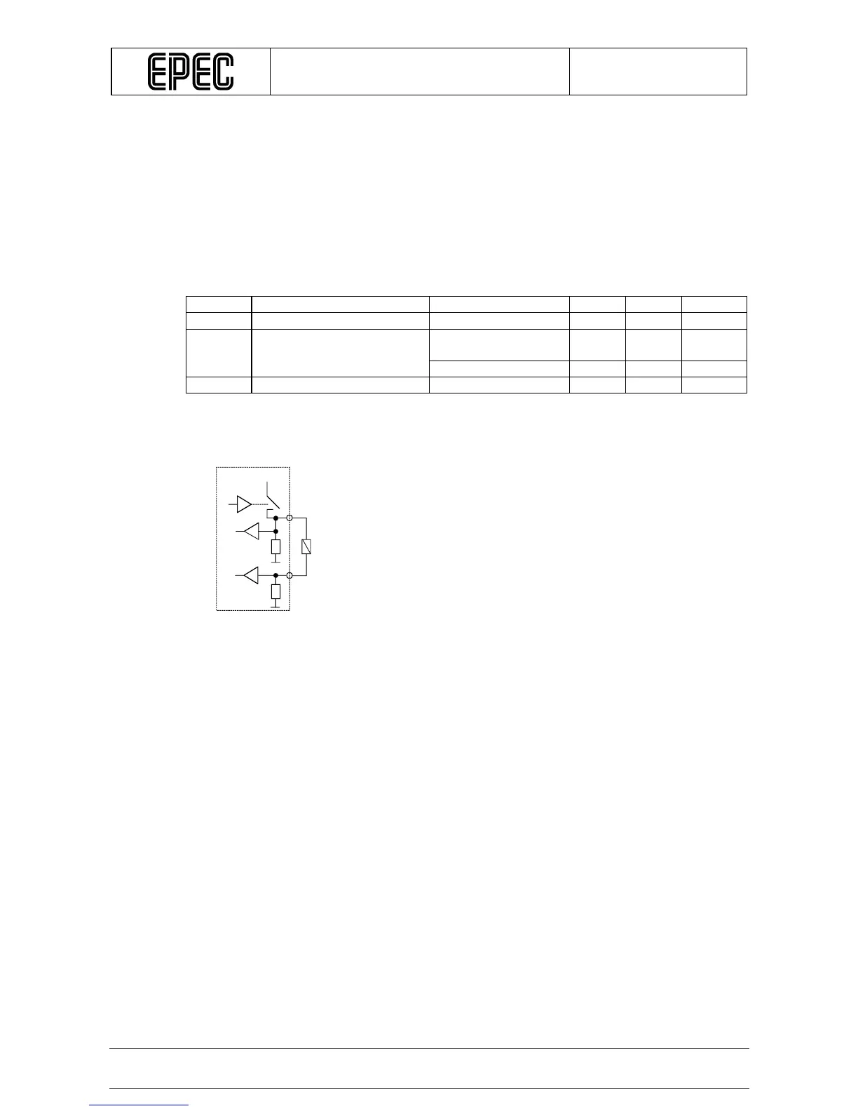
Connection Principle
A pin where the upper wire of the load is connected is PWM output / digital output. This
illustrates the normal way to connect loads when load current measurement is desired.
+24V
Module
Load