Technical Manual 5050 / MAN000539 Page 19/92
Epec Oy reserves all rights for improvements without prior notice
Epec Oy Postiosoite/Postal address Puhelin/Phone Fax Internet
Tiedekatu 6 PL/P.O.Box 194 +358-(0)20-7608 111 +358-(0)20-7608 110 www.epec.fi
FIN-60320 Seinäjoki FIN-60101 Seinäjoki, Finland
The FET outputs are grouped into pairs:
• The maximum continuous current for a single output in the pair is 2,5 A.
• The maximum continuous current for the pair is 4 A.
The pairs are indicated with upper case characters in the pin table's Group column
in section
Pinout Map
Input (DI)
• This pin can be used as a digital input (DI)
• A pin of this type can also be used as an input by using the output state monitoring feature.
• In this case, the output functionality of the pin must be kept in the off state.
• It must be taken care in system design that the output unintentionally switching to on state
causes no harm to the system.
• This pin can be used also with NPN-type sensors – sensors with open collector/open drain.
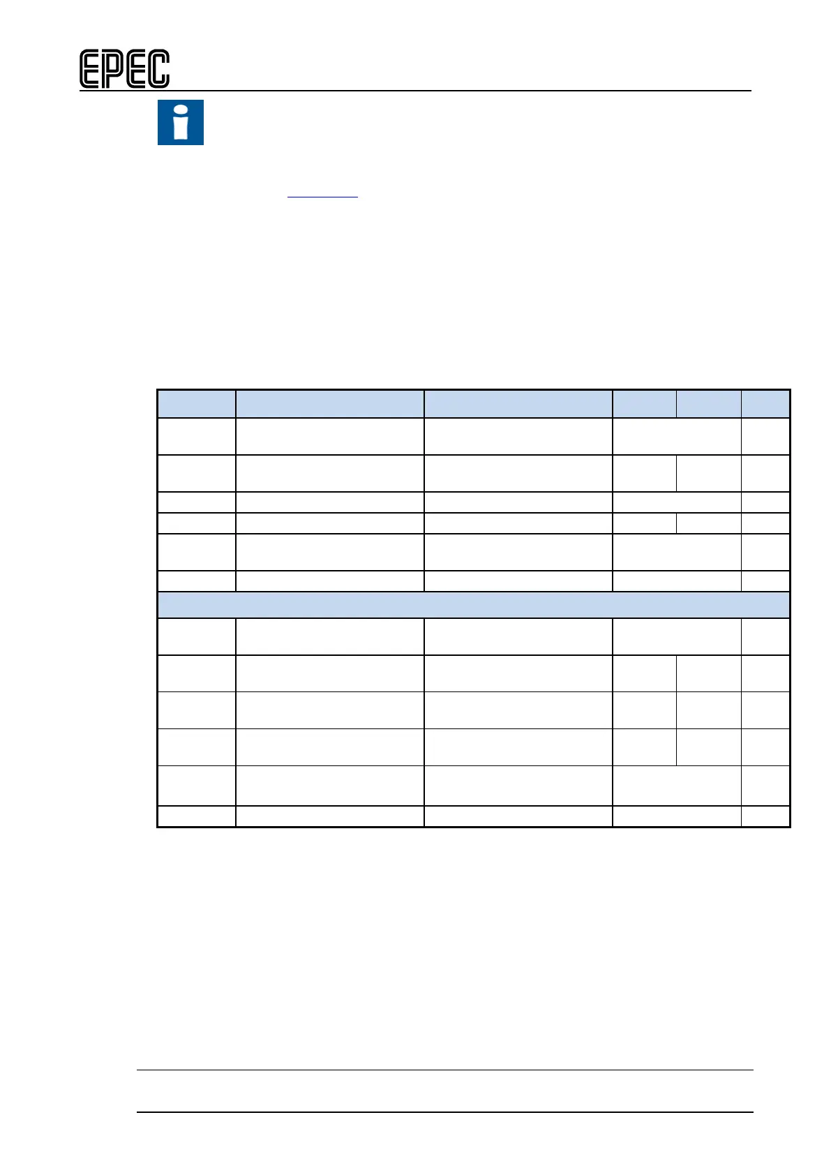
Electrical characteristics
Symbol Parameter Conditions Min Max Units
V
Level
Output voltage
Output Off, Pull-up selected,
typ. 8,3 V
I
o
Nominal Output Current
Output On
0 2,5 A
Internal current limitation
Duty
PWM
PWM
(Note 2, 10) 0 to 100 %
Digital status input
R
I
Input Resistance
Output Off, Pull-up resistor
typ. 13 kΩ
V
IH
Digital status input
Output Off (Note 6) 3,2 V
V
IL
Digital status input
Output Off 1,9 V
V
I-range
Input voltage range (Note 11) -0,5
U
in
+
V
t
I
Digital Status Input
Pulse Width
(Note 2, 4, 8)
> tC ms
Note 1: Frequency of a (PWM) Pulse Width Modulation is = 1 / Period
Note 2: The duty cycle is defined as the percentage of digital ‘high’ to digital ‘low’ signals
present during a PWM period.
Note 3: The PWM resolution is defined as the maximum number of pulses that you can pack
into a PWM period.
Note 4: tC denotes software cycle time.
Note 5: Current limit for short circuit protection to protect cabling and to limit internal power
dissipation.
Note 6: Exceeding the max value might cause damage to input.
Note 7: The maximum output current depends on the load, PWM frequency and temperature.
Note 8: Pulse width must be greater that the software cycle time. For example with 50/50 pulse
ratio, the pulse frequency is 1 / (2*pulse width)
 Loading...

