24
7.1 Connector Summary
7.1.1 Major Component Unit
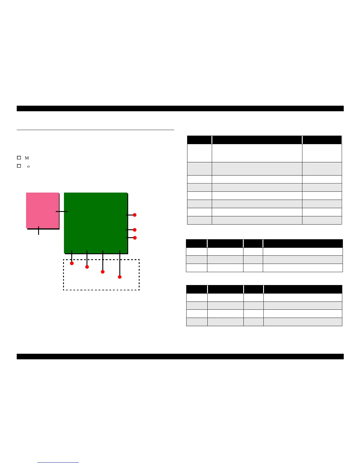
The Major component units of this printer are as follows.
o
Main Board (C383MAIN)
o
Power Supply Board (C383PSB/PSE)
The figure below shows how these components connect.
Figure 7-1. Connection of the Major Components
See the following tables for the connector summary for the C383MAIN board and each
connector’s pin alignment.
CN8, CN9 CN12 CN4
Parallel I/F
CR Motor
Printhead
PF Motor
C383MAIN
CN7
CN1
CN10
HP/PE Sensor
C383PSB/PSE
CN2
CN1
AC Power
Printer Mechanism
USB
CN3
C383 PNL
CN11
Table 7-1. Connector Summary for C383MAIN/MAIN-B
Connector Function Table to refer to
CN1 For connection with the parallel interface
Refer to
“IEEE1284.4
Protocol” on page 19
CN3 For connection with the USB
Refer to “USB” on
page
CN4 For connection with the HP/PE sensor Table 7-2
CN7 For connection with the PF motor Table 7-3
CN8, CN9 For connection with the printhead Table 7-5
CN10 For connection with the power supply board Table 7-6
CN11 For connection with the C383PNL board Table 7-x
CN12 For connection with the CR motor Table 7-8
Table 7-2. CN4 - HP/PE Sensor
Pin Signal Name I/O Function
1 HPPE In Sensor detect signal
2 GND --- Ground
3 HPPEV --- Sensor Power Supply
Table 7-3. CN7 - PF Motor
Pin Signal Name I/O Function
1 PFA Out Phase drive signal (A)
2 PFB Out Phase drive signal (-A)
3 PF-A Out Phase drive signal (B)
4 PF-B Out Phase drive signal (-B)