EPSON Stylus COLOR 680/777/77i Revision B
Operating Principles Electrical Circuit Operating Principles 43
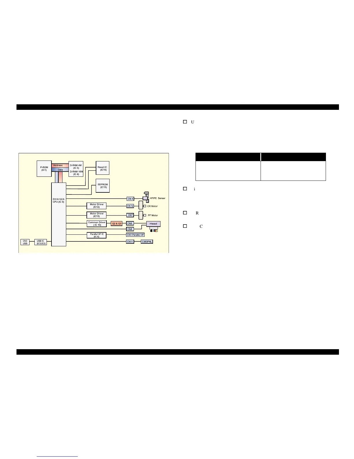
2.2.2 C383 MAIN Board
The printer mechanism is controlled by C383 MAIN.
See Figure for the C383 MAIN board block diagram.
Figure 2-17. Block Diagram for the C383 MAIN Board
Following shows you the major characteristic of this main board.
o
Use of the 3.3V chips in the logic circuit
The 3.3 V regulator (IC11) on the C383MAIN produces 3.3 V by pressuring down
the 5.5 VDC, also generated on this board, to drive several chips. See the table
below that separately shows the chips driven by the +5V and +3V.
Table 2-6. 3.3V Drive Chips & 5.5V Drive Chips
o
Timer IC & Lithium battery are not mounted
Unlike the previous products, the Timer IC and the Lithium battery are not
mounted on the Main board. So, this product perform the Power-on cleaning or
Timer cleaning based on the time command which is sent from the printer driver.
o
D-RAM
4Mbit and 16Mbit D-RAMS are mounted on the Main board.
o
One CPU controls the all function on the main board.
+5V 3.3V
Sensors
I/F Circuit
PNL Board
CPU
P-ROM
D-RAM