EPSON AcuLaser C1900/AcuLaser C900 Revision B
Troubleshooting Status Display (AcuLaser C900) 146
ERROR CODE: 6011 “EXHAUST FAN MOTOR ERROR”
Detection Timing
When the Exhaust Fan Motor (M6) does not operate at turning on the main switch.
Solution
Parts which can cause the alarm:
• Exhaust Fan Motor (M6)
• Engine Board (PWB-A)
• Power Supply Unit (PU)
ERROR CODE: 6012 “POWER COOLANT FAN ERROR”
Detection Timing
When the Power Coolant Fan Motor (M4) does not operate at turning on the main switch.
Solution
Parts which can cause the alarm:
• Power Supply Cooling Fan Motor (M4)
• Engine Board (PWB-A)
• Power Supply Unit (PU)
ERROR CODE: 6014 “FUSER COOLING FAN MOT ERROR”
Detection Timing
When the Fuser Cooling Fan Motor (M5) does not operate at turning on the main
switch.
Solution
Parts which can cause the alarm:
• Fuser Cooling Fan Motor (M5)
• Engine Board (PWB-A)
• Power Supply Unit (PU)
ERROR CODE: 6016 “POLYGON MOTOR ERROR”
ERROR CODE: 6018 “LASER ERROR”
Detection Timing
When the Polygon Motor does not operate, or the laser diode (LD) does not emit
the laser beam.
Solution
Electric parts which can cause the trouble:
• Print Head Unit
• Engine Board (PWB-A)
• Power Supply Unit (PU)
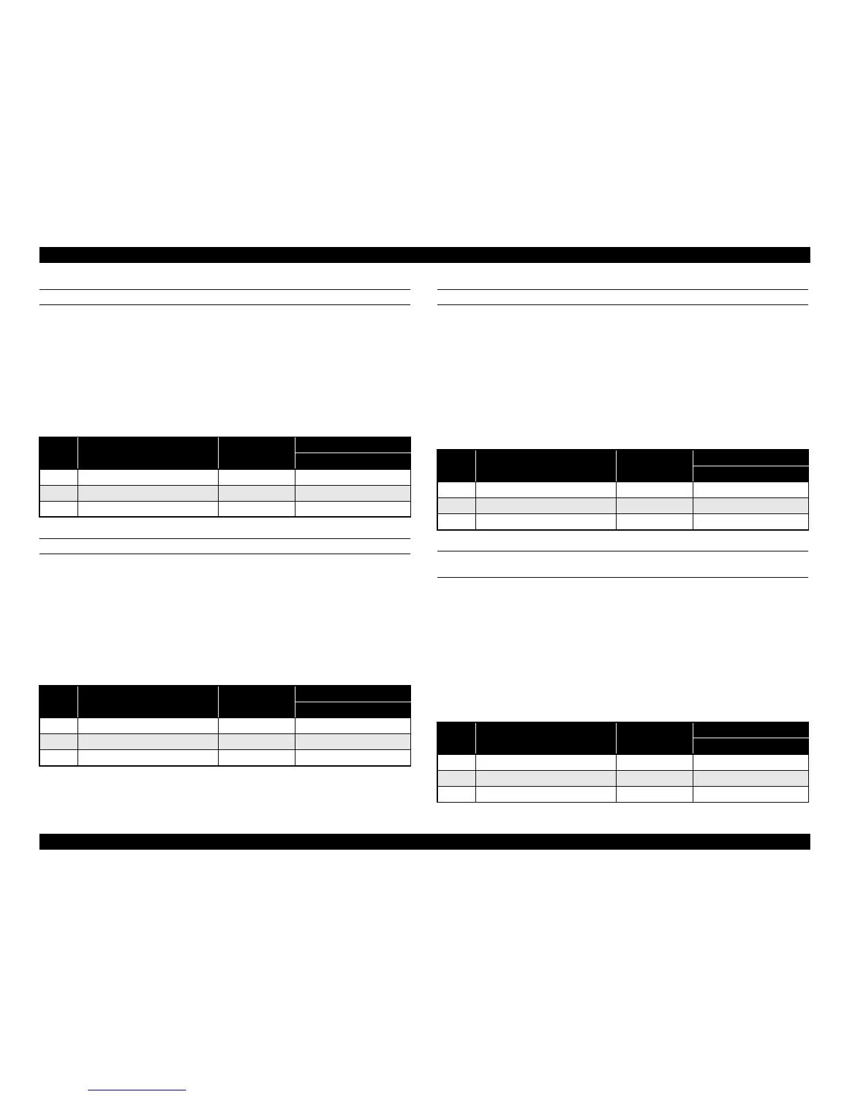
Table 3-24.
Step Action Refer to
WARNING DIAGRAM
Control Signal
1 Check the operation of M6. p.163 M6_REM
2 Replace the PU. - -
3 Replace the PWB-A. - -
Table 3-25.
Step Action Refer to
WARNING DIAGRAM
Control Signal
1 Check the operation of M4. p.163 M4_REM
2 Replace the PU. - -
3 Replace the PWB-A. - -
Table 3-26.
Step Action Refer to
WARNING DIAGRAM
Control Signal
1 Check the operation of M5. p.163 M5_REM
2 Replace the PU. - -
3 Replace the PWB-A. - -
Table 3-27.
Step Action Refer to
WARNING DIAGRAM
Control Signal
1 Replace the print head unit. - -
2 Replace the PU. - -
3 Replace the PWB-A. - -
 Loading...


