EPSON AcuLaser C1900/AcuLaser C900 Revision B
Disassembly and Assembly Printer Main Parts Disassembly and Assembly 202
4.5.20 Rack
1.
Remove the High Voltage Unit (HV). (p.188)
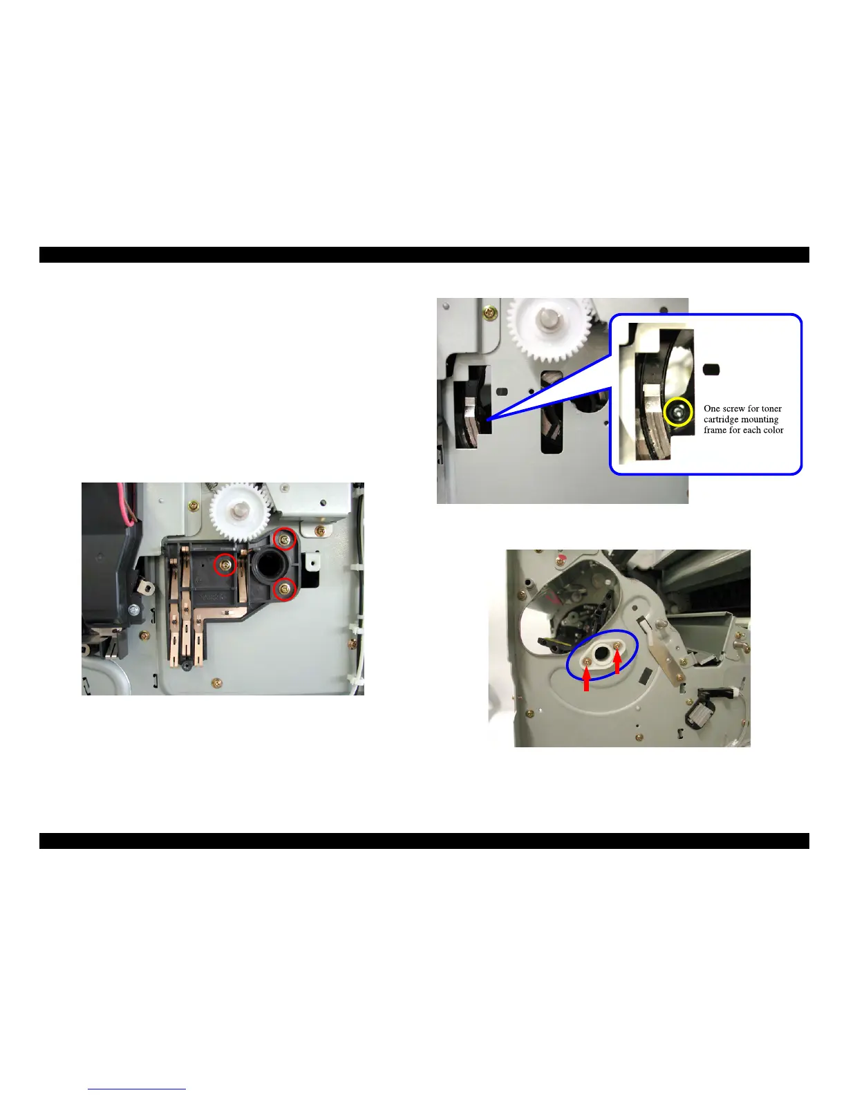
2. Remove the HV Contact Assy. (3 screws) (See
“Figure 4-57 (p.202)”)
3. While supporting it with your hand, rotate the Rack to a position where you can see
through the cut area of the frame the screw securing a toner cartridge mounting frame
on the Rack.
4. Remove the screws securing the toner cartridge mounting frame. (4 screws in total)
(See
“Figure 4-58 (p.202)”)
5. Remove the Rack Fulcrum Cover. (2 screws) (See
“Figure 4-59 (p.202)”)
6. Separate the toner cartridge mounting frame from the Rack and take them out through
cut areas of the frame, respectively. (See
“Figure (p.202)”)
Figure 4-57. Removing the HV Thermal Assy
Figure 4-58. Removing the Screws securing the Toner Cartridge Mounting Frame
Figure 4-59. Removing the Rack Fulcrum Cover
 Loading...


