EasyManuals Logo

Epson DFX-9000 Repair Guide

Epson DFX-9000
223 pages
To Next Page IconTo Next Page
To Previous Page IconTo Previous Page
Page #25 background imageLoading...
Page #25 background image
Epson DFX-9000 Field Repair Guide 3/29/07
Component Replacement Printer Component, Software Item, LCD Display, Printer Button Page 16.
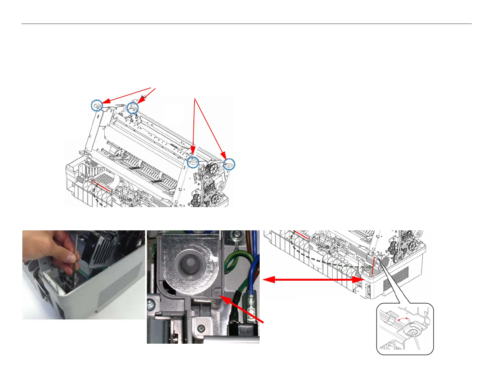
Mechanism Removal
Note: Perform the Upper Case Removal procedure before performing the steps below. Steps 2 - 4 refer
to “Rear Grabs”, “Tilt Bar”, and “Grommet”. Refer to the figure below for the location of these
items.
When performing Step 4, ensure that the Tilt Bar is positioned as indicated in the figure below to
prevent damage to the wiring harness located near the Grommet.
Front and Rear “Grabs”
Place bottom of
Tilt Bar here
Place
Place bottom of
Tilt Bar in the
small square area

Table of Contents

Other manuals for Epson DFX-9000

Questions and Answers:

Question and Answer IconNeed help?

Do you have a question about the Epson DFX-9000 and is the answer not in the manual?

Epson DFX-9000 Specifications

General IconGeneral
ColorNo
Built-in barcodesCode 39, POSTNET, UPC-A, UPC-E
Maximum resolution240 x 144 DPI
Maximum print sizeA4 (210 x 297 mm)
Standard interfacesSerial
Dimensions (WxDxH)700 x 378 x 363 mm
Power requirements100-240V, 50-60Hz
Connectivity technologyWired
Compatible operating systemsMicrosoft Windows 95 / 98 / 2000 / Me / XP/ Windows NT 4.0
Sound pressure level (printing)58 dB
Mean time between failures (MTBF)20000 h
Sustainability certificatesENERGY STAR
Power consumption (standby)1.85 W
Power consumption (typical)7.5 W
Operating temperature (T-T)5 - 35 °C
Operating relative humidity (H-H)10 - 80 %

Related product manuals