Maintenance 7. Arm #3
G3 Rev.14 127
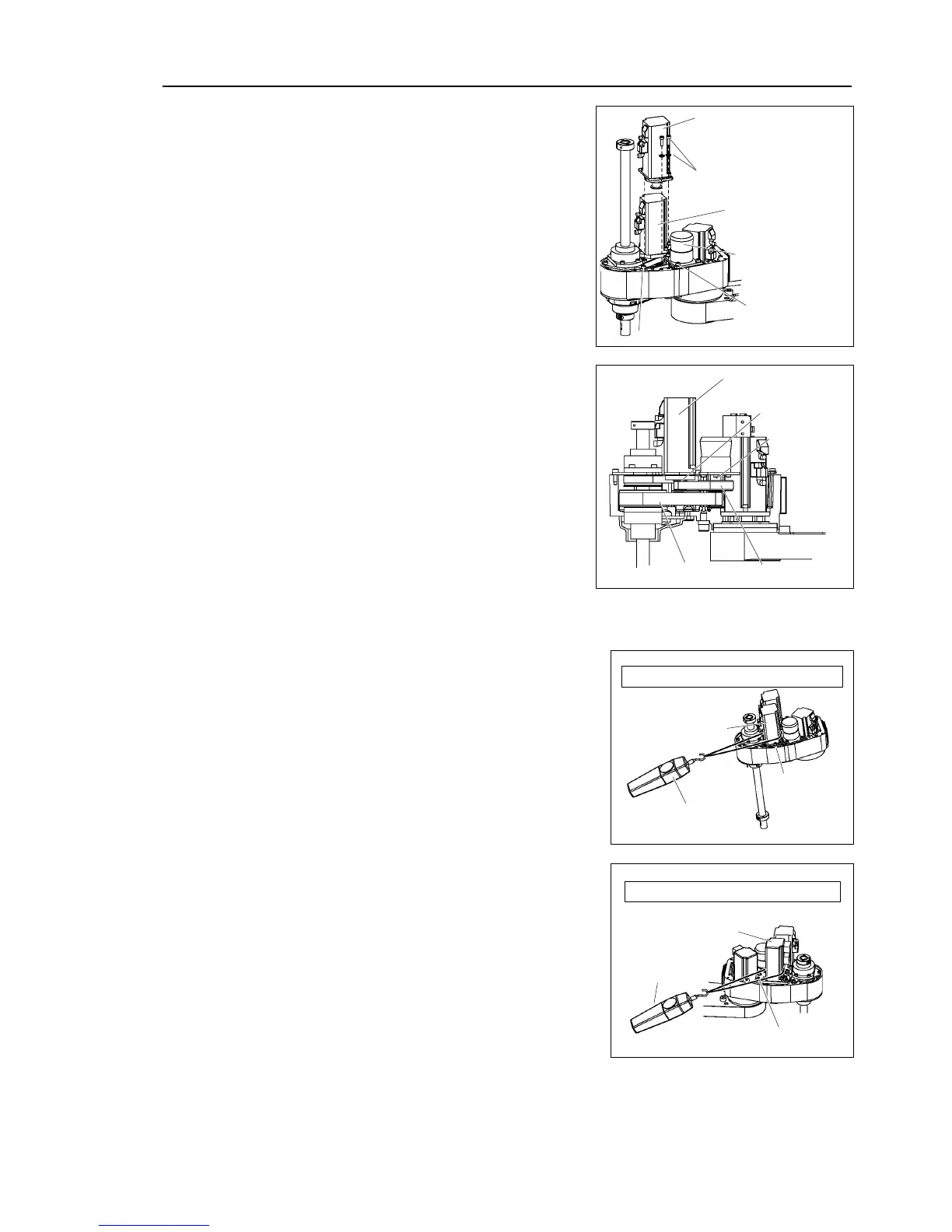
the U2 belt and place the
Joint #4 motor unit on the Arm #2 surface.
Make sure the motor cables face to the
end of the arm.
Joint #4
intermediate shaft
Loosely secure the Joint #4 motor unit to
Arm
the motor unit can be moved
, and it will not tilt when
f the unit is secured too loose or too tight,
the spline plate to Arm #2.
After moving the shaft up and down several times, secure the spline plate to Arm #2.
Apply the proper tension to the U1 belt, and
then secure the Joint #4 motor unit.
a suitable cord or string
around the Joint #4 motor unit near its
mounting plate
. Then, pull the cord using a
gauge or similar tool to apply the
specified tension shown in the figure on the
right
U1 belt tension = 74 N (7.5 ± 0.5 kgf)
then secure the Joint #3 motor unit.
a suitable cord or string
around the Joint #3 motor unit near its
mounting plate
. Then, pull the cord using a
gauge or similar tool to apply the
specified tension shown in the fi
Z belt tension = 74 N (7.5 ± 0.5 kgf)
.
Connectors: X231, X241, X31, X32, X41

 Loading...


