Maintenance 4. Cable
80
LS20-B R ev.4
Pass the new cables through the Cable Duct Unit. Then, rotate the fittings to secure the
cables.
Pass the cables in the Duct Plate side through the Duct Plate and nut and turn the fittings
to secure the cables.
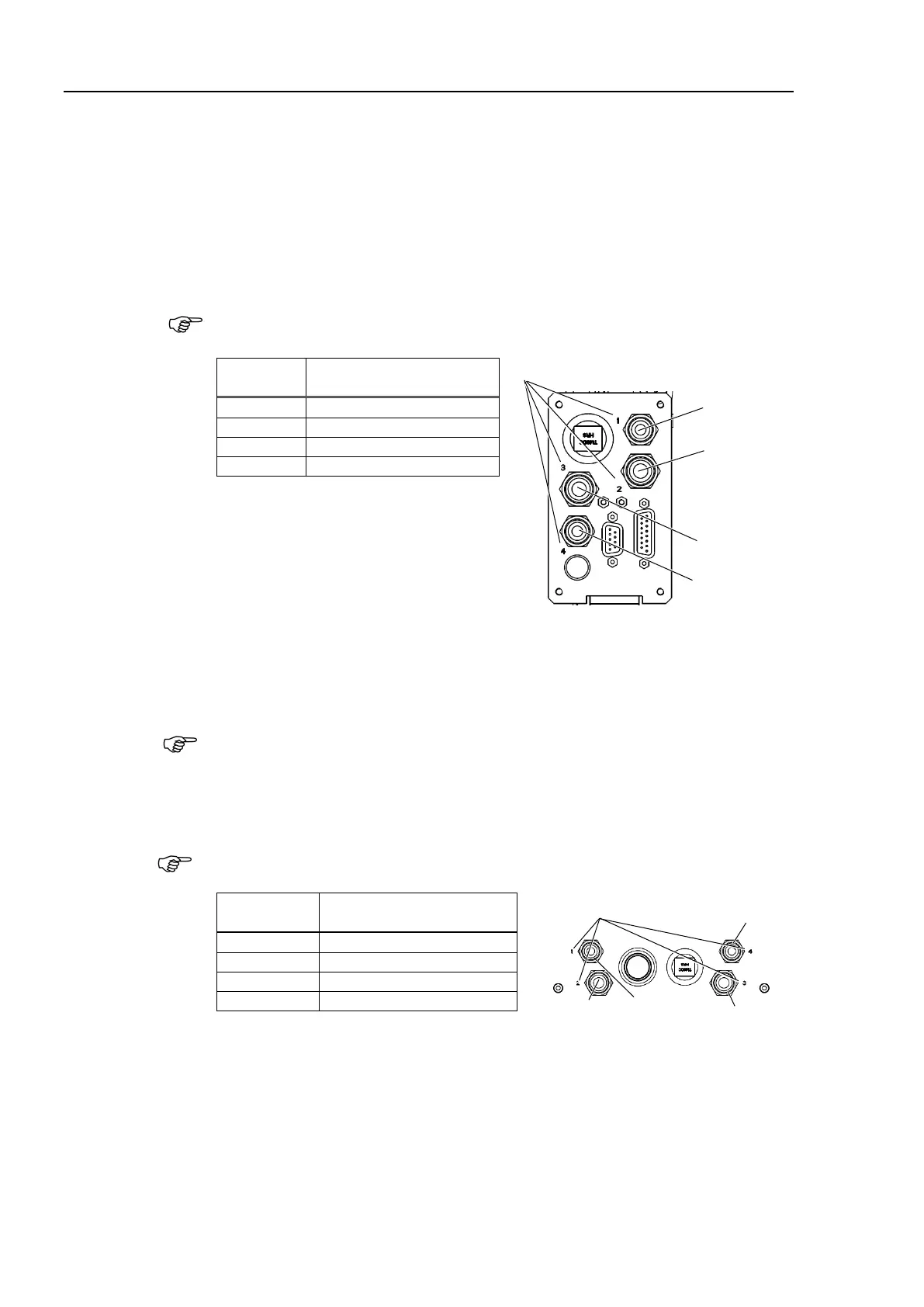
parts to the Connector Plate.
Pneumatic tube, D-sub cable, Ethernet cable (RJ45), ground wire (×7)
-B series manipulators are white. See the
table below for connection
of pneumatic tube to fittings.
Pneumatic tube
(Color / Outer Diameter)
Fitting No.
Blue: ø6
Black: ø8
Blue: ø8
Black: ø6
Connect two connectors on t
he Base side.
Connectors: X41, X211
ind the cables with a new wire tie as before in the removal step (8).
Fix the short flexible tube shipped with the cable unit with the wire tie at the upper side
of the metal duct.
parts to the User Plate.
Pneumatic tube, D-sub cable, Ethernet cable (RJ45)
-B series manipulators are white. See the
table below for connection
of pneumatic tube to fitting
s.
Fitting No.
Pneumatic tube
(Color / Outer Diameter)
Blue: ø8
Fitting No.
Blue: ø6
Black: ø8
Black: ø6
F
or the details, refer to Maintenance: 3.6 User Plate.
following connectors.
Connectors: X22, X33,X42, X43, X44, X51, BR3, BR4, X221, X231, X241
two ground wires in the Arm side to the Joint #3 Motor Plate and Duct Plate.

 Loading...


