Home
Epson
Control Unit
RX8130CE
Page 13
Epson RX8130CE - Page 13
69 pages
Manual
Save Page as PDF
To Next Page
To Next Page
To Previous Page
To Previous Page
Loading...
9. Electrica
l Character
istics
RX8130CE
Jump to
Top
/
Bottom
ETM50E-07
Seiko Ep
son Cor
poration
12
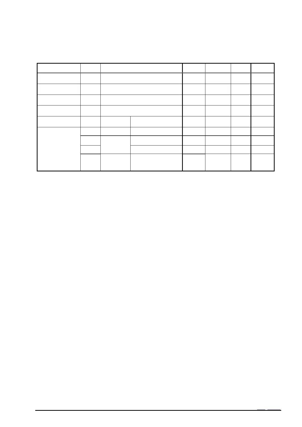
Table 6 D
C characteristi
cs(2)
Unless otherwise specified GND
=
0
V
V
BAT
= V
DD
= 1.1V~5.5V V
IO
=1.6V ~5.5V
Ta
=
40
C
to
+85
C
Item
Symbol
Condition
Min.
T
y
p.
Max.
Unit
V
OUT
output voltage
1
V
VOUT1
V
DD
= 3.0 V
I
OUT
= 1
mA
V
DD
-0.06
V
V
OUT
output voltage
2
V
VOUT2
V
BAT
= 3.0 V
I
OUT
= 0.1
mA
V
BA
T
-0.02
V
High-level
input voltage
V
IH1
SCL
, SDA
0.8
V
IO
5
.5
V
Low
-level
input voltage
V
IL
SCL, SDA
GND
0.3
0.2
V
IO
V
High-level
output voltage
V
OH
FOUT
I
OH
= -1 mA
V
IO
–
0.5
V
IO
V
Low
-level
output voltage
V
OL1
FOUT
I
OL
= 1 mA
GND
GND+0.5
V
V
OL2
/RST
,/IRQ
V
IO
= 5 V, I
OL
= 1 mA
GND
GND+0.2
5
V
V
OL3
V
IO
= 3 V, I
OL
= 1 mA
GND
GND+0.4
V
V
OL4
SDA
V
IO
2 V, I
OL
= 3
mA
GND
GND+0.4
V
12
14
Table of Contents
Main Page
ETM50E Revision History
3
Table of Contents
5
Overview
7
Block Diagram
7
Terminal Description
8
Terminal Connections
8
Pin Functions
8
Examples of External Connection
9
Examples of Power Supply Connection
9
External Dimensions / Marking Layout
10
Absolute Maximum Ratings
11
Recommended Operating Conditions
11
Frequency Characteristics
11
Electrical Characteristics
12
Interface Timing When Power Is Turned on / off
16
Restrictions of I 2 C-Bus Interface in the Initial Power on
16
Precautions for Power on / off
16
VDD on / off When Using Power Switching (INIEN = 1)
17
VDD on / off When Power Switching Is Not Used (INIEN = 0)
17
Reference Information
18
Application Notes
19
Overview of Functions and Registers
20
Overview of Functions
20
Register Table
21
Register Initial Value and Read/Write Operation Table
22
Description of Registers
23
Clock and Calendar Registers (0H ~ 16H)
23
RAM Registers (20H ~ 23H)
23
Alarm Registers (17H ~ 19H)
23
Timer Setting and Timer Counter Register for Wakeup Timer (1Ah ~ 1Eh)
23
Function-Related Register 1 (1Ch ~ 1Eh)
23
Function-Related Register 2 (1Fh)
24
Digital Offset Register (30H)
24
Functions
25
Clock Calendar Explanation
25
Clock Counter
25
Week Counter
26
Calendar Counter
26
Wakeup Timer Interrupt Function
27
Related Registers for Function of Wakeup Timer Interrupt Function
27
Wakeup Timer Start Timing
30
Wakeup Timer Interrupt Interval (Example)
31
Diagram of Wakeup Timer Interrupt Function
31
Alarm Interrupt Function
33
Related Registers for Alarm Interrupt Functions
33
Examples of Alarm Settings
34
Time Update Interrupt Function
36
Related Registers for Time Update Interrupt Functions
36
Time Update Interrupt Function Diagram
37
Oscillation Stop Detection Function
38
Related Registers for Oscillation Stop and Voltage Low Detect Function
38
FOUT Function
38
FOUT Control Register
38
FOUT Function Table
38
Battery Backup Switchover Function
39
Description of Battery Backup Switchover Function
39
Reference Characteristics of Switching Elements
39
Reference Characteristics of the Charge Current
40
Re-Chargeable Battery Voltage Current Features
40
Related Register of Battery Backup Switchover Function
41
Detection Voltage Setting
46
Power Supply Control
48
Main Power Supply
49
Backup Power Supply
50
BAT ) Voltage and a Charge State
50
Reset Output Function
51
Digital Offset Function
52
Digital Offset Register
52
Effect of the Digital Offset Function to Other Functions
53
Flow-Chart
54
Initializing Example
54
Software Reset
55
Example of Initialization Routine
56
Example of Initialization Routine (Only Clock Usage)
57
The Setting of the Clock and Calendar
57
The Reading of the Clock and Calendar
58
Setting Example of the Wakeup Timer Interrupt Function
58
Setting Example of the Alarm Interrupt Function
59
Serial Communication
60
Overview of I C-Bus Interface
60
Data Transfers
60
Starting and Stopping I C-Bus Communications
60
Slave Address
60
System Configuration
61
I 2 C-Bus Protocol
62
Circuit Diagram Connection
64
Typical MCU Connection
64
Khz Oscillator Application Connection
65
Tables
66
Figures
67
Contacts
69
Related product manuals
Epson RX8111CE
67 pages
Epson RX8900SA/CE
43 pages
Epson RC+ 7.0
42 pages
Epson RTC-72421
29 pages
Epson UB-E03
8 pages