19 Serial communication
RX8130CE Jump to Top / Bottom
ETM50E-07 Seiko Epson Corporation 60
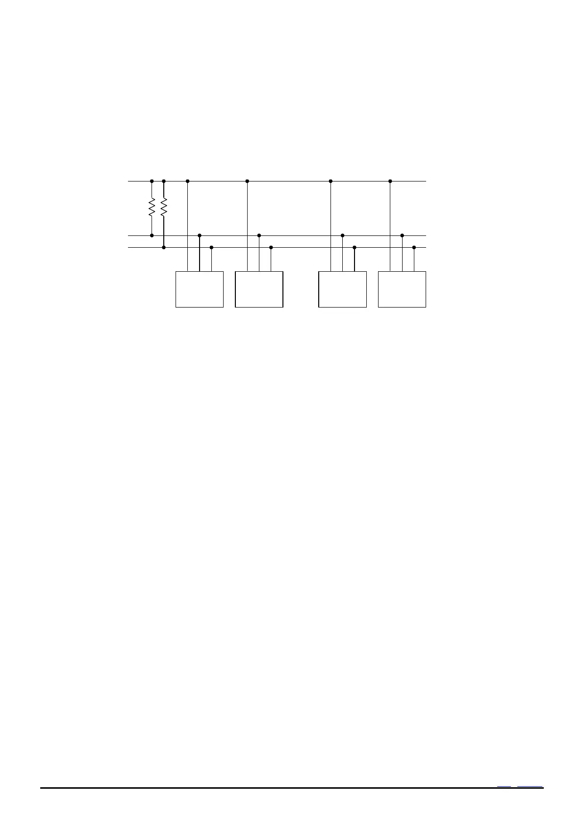
19.5 System configuration
All ports connected to the I
2
C-Bus must be either open drain or open collector ports in order to enable AND connections
to multiple devices.
SCL and SDA are both connected to the VIO line via a pull-up resistance. Consequently, SCL and SDA are both held at
high level when the bus is released (when communication is not being performed).
Figure 48 I
2
C-Bus connection
Any device that controls the data transmission and data reception is defined as a "Master".
and any device that is controlled by a master device is defined as a “Slave”.
The device transmitting data is defined as a “Transmitter” and the device receiving data is defined as a receiver”
In the case of this RTC module, controllers such as a CPU are defined as master devices and the RTC module is
defined as a slave device. When a device is used for both transmitting and receiving data, it is defined as either a
transmitter or receiver depending on these conditions.