15 Battery backup switchover function
RX8130CE Jump to Top / Bottom
ETM50E-07 Seiko Epson Corporation 38
15 Battery backup switchover function
15.1. Description of Battery backup switchover function
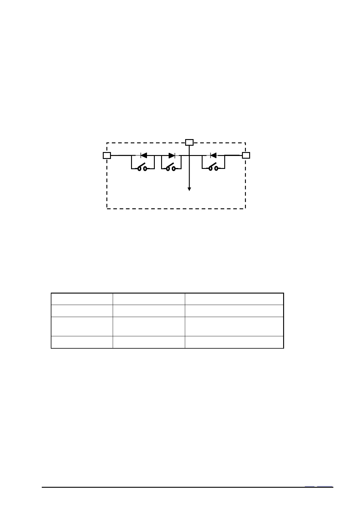
This function consists of a supply voltage detector "VDET" which detects if the supply voltage of the main
power source connected to "VDD" drops below a threshold (V
DET
2), and three MOS switches (SW1,SW2A and
SW2B) located between the main power-source pin "VDD" and the backup power supply pin "VBAT". (Figure 26
Battery backup switchover block diagram)
The MOS-switches SW1, SW2A and SW2B are activated according to the result of the supply-voltage
detection of VDET2 and the RTC changes the operating modes between normal mode (RTC power supply =
V
DD
) or backup mode (RTC power supply = V
BAT
).
The RTCs backup function is built in a way to prevent reverse current flow from V
BAT
to V
DD
. While in backup-
mode, the I2C-bus and FOUT function are switched off and related terminals switched to Hi-Z.
Figure 26 Battery backup switchover block diagram
15.2 Reference characteristics of switching elements.
Table 33 Reference characteristics of switching elements.
Use a secondary battery, EDLC, etc, with the charge current of 40 mA or less.