1. Overview
RX8130CE Jump to Top / Bottom
ETM50E-07 Seiko Epson Corporation 6
Build-in backup battery charge control function
SERIAL-INTERFACE REAL TIME CLOCK MODULE
Built in frequency adjusted 32.768 kHz crystal unit.
Interface type : I
2
C-Bus interface (up to 400 kHz)
Wide operating voltage range : 1.6Vto5.5V
Wide timekeeper voltage range : 1.1Vto5.5V
Auto power switching function : Switchover by main power supply monitor.
Backup battery charge control function : For rechargeable lithium batteries.
Low leak current : A leak current from a backup power supply pin. 5nA Max.
Reset function : At low supply voltage, external reset signal is generated.
Low voltage detection : Supply voltage and backup voltage detection
Time correction : Digital offset function
The various function including full calendar, alarm, timer, etc.
1. Overview
RX8130CE is a real-time clock module of the I
2
C serial interface system, 32.768 kHz crystal and oscillator is built-in it.
The real-time clock function incorporates not only a calendar and clock counter for the year, month, day, day of the
week, hour, minute, and second, but also a time alarm, wakeup timer, and time update interruption, among other
features. By the backup battery charge control function and the interface power supply input pin, RX8130CE can support
various power supply circuitries.
All these many functions are implemented in a thin, compact ceramic package, which makes it suitable for various kinds
of small electronic devices, low power IoT devices etc.
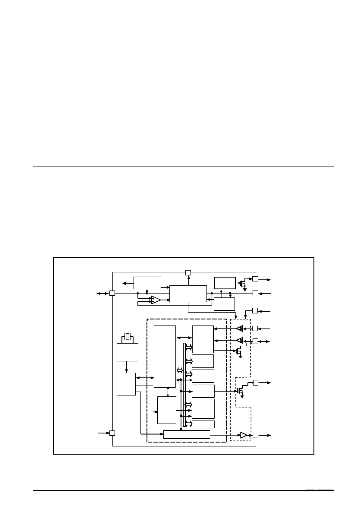
2. Block Diagram