18. Flow-chart
RX8130CE Jump to Top / Bottom
ETM50E-07 Seiko Epson Corporation 55
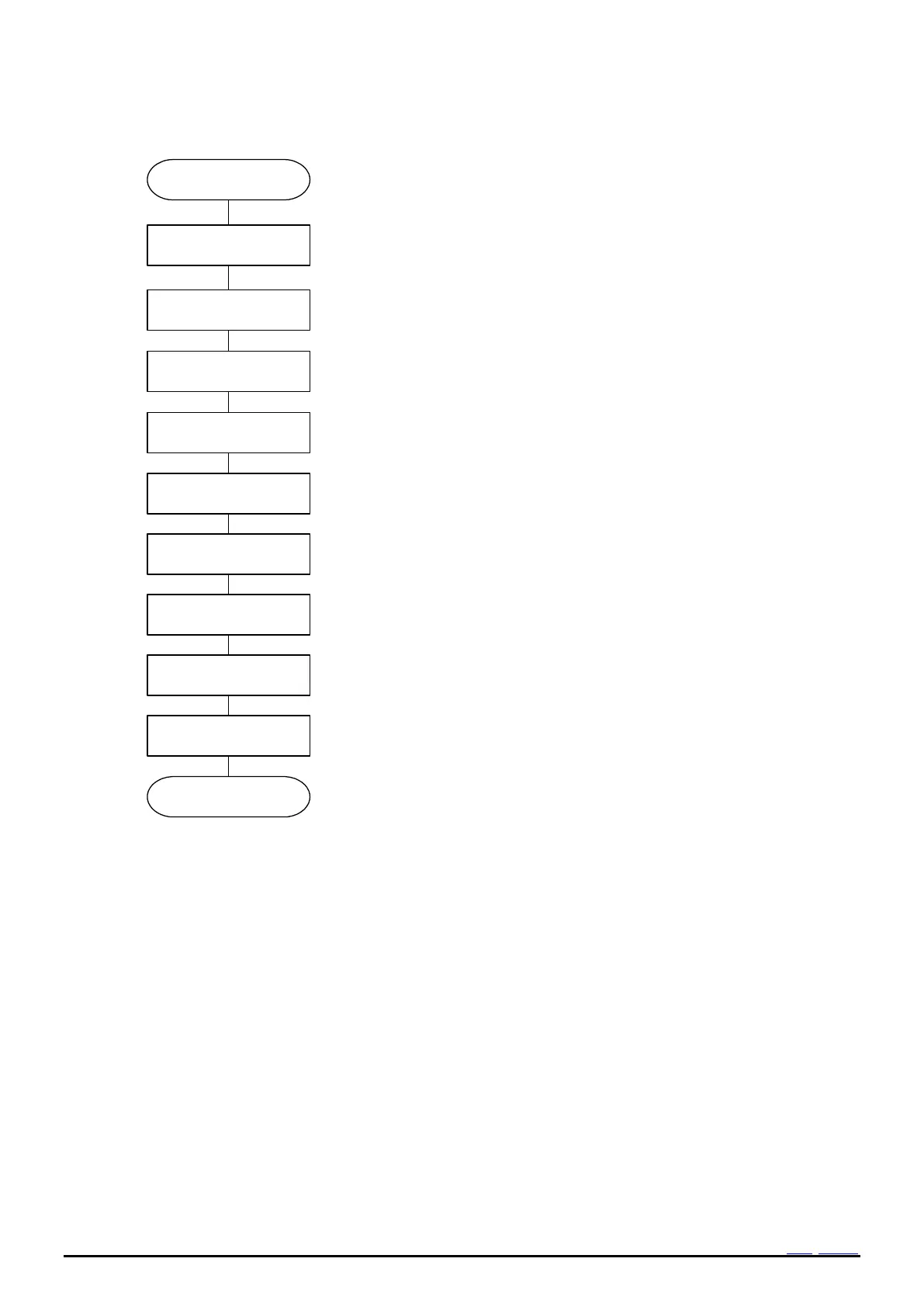
18.3 Example of Initialization routine
Clear VLF bit to “0”.
State of VLF=1 is held even if it 0 clear until oscillation start. When initialize
it without waiting for an oscillation start, Clear VLF bit after an oscillation
start.
Set INIEN to 1.
When it is used in INIEN=0, please set it in INIEN=0 again after setting
INIEN to 1 once.
Set time and
calendar.10h16h
Set the present time.
Setting the present time concerned.
See 14.1. Clock calendar explanation.
Configure the Alarm interrupt function.
When the alarm interrupt function is not being used, the Alarm registers
can be used as a RAM register. In such cases, be sure to write "0" to the
AIE bit.
Configure the interval timer function.
When the interval Timer function is not being used, the Timer Counter
register can be used as a RAM register. In such cases,
stop the interval timer function by writing "0" to the TE and TIE bits.
When initialization is finished, be sure to set STOP bit to “0”.
Clear TE bit to “0”.
Set FSEL1,0 bitoptionally.
Update interrupt function
Configure the Update interrupt function.
Setting of the digital offset
Reg30h
When the digital offset function is not being used, write 0 in the DTE bit.
Clear TEST bit to 0.
Clear AIE, TIE, UIE for inhibit interrupt output of suddenness.
Figure 41 Example flow (Initialization)