14. Functions
RX8130CE Jump to Top / Bottom
ETM50E-07 Seiko Epson Corporation 37
14.5. Oscillation stop detection function
This flag bit indicates the retained status of clock oscillation stop. Its value changes from "0" to "1" when data
loss might have occurred due to clock oscillation stop, power on resetting. Once this flag bit's value is "1", its
value is retained until a "0" is written to it.
During the initial power-on (from 0V) and/or if the value of the VLF bit is "1", be sure to initialize all registers
before using them.
14.5.1. Related registers for Oscillation stop and Voltage low detect function.
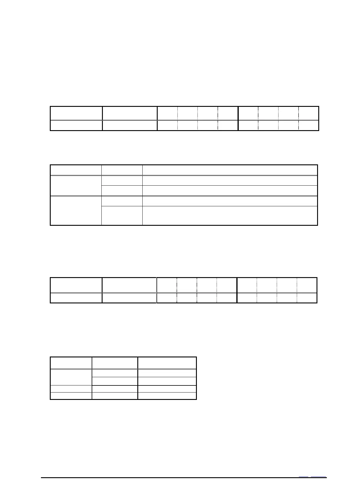
1) VLF bit
Table 31 Oscillation stop detection flag
The VLF is cleared to 0 and waiting for next low voltage detection.
Invalid (writing 1 will be ignored)
Oscillation status is normal, RTC register data are valid.
Oscillation stop is detected, RTC register data are invalid.
Should be initialized of all register data.
VLF is maintained till it is cleared by zero.
14.6. FOUT function
The clock signal can be output via the FOUT pin. Output is stopped upon detection of the voltage drop below
VDET1In this case pin output becomes Hi-z.
14.6.1. FOUT control register.
14.6.2. FOUT function Table.
3) FSEL1,FSEL0 bit
Table 32 FOUT Frequency selection
At the time of the initial power-on, “0” is set to FSEL1, FSEL0 by Power-On-Reset..
Note: The effect of STOP bit to FOUT functions.
When STOP = "1", 32.768 kHz and 1024 Hz output is possible.
But 1 Hz output is disabled.