VT6L Maintenance 13. Joint #5
108 VT series Maintenance Manual Rev.2
Pass the timing belt through the motor pulley and
loosely
to the Arm #4.
Hexagon socket head cap bolts: 3-M4×20
(with slotted hole washer)
that the gear grooves of the timing belt are fit
into those of the pulley completely.
When securing the motor unit loosely, make sure that the
motor unit can be moved by hand and it does not tilt when
being pulled. If the unit is secured too loose or too
tight,
the belt will not have proper tension.
The direction to install the motor is the direction
in which the connector of the motor faces Joint
#5 side.
Be careful for the
installation direction
Apply proper tension to the motor unit and fix it.
Joint #5 timing belt tension: 23 - 36 N
Belt tension meter setting values
Weight: 2.5g/mm width×m span
Width: 6.0mm
Span: 184mm
Hexagon socket head cap bolts: 3-M4×20 (with slotted hole washer)
Tightening torque: 4.0 ± 0.2 N·m
Jumping (position gap) may occur if the value is below the lower limit.
Vibration (abnormal noise) or reduction in life of the parts may occur if the value
exceeds the upper limit.
When you replace with a new belt, belt extends and the belt tension may decrease in the
initial stage. Make sure to operate the robot two to three days and check the belt
tension again
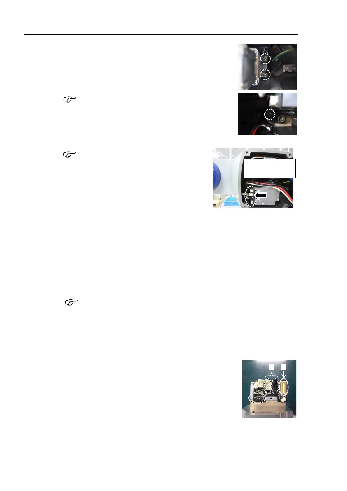
following connectors of the motor.
A: Signal cable connectors (for motor × 2)
B: Signal cable connector (for AMP board)
Connector for the signal cable connector (for motor) is the
same color.

 Loading...


